Adjustable Jig Eases PCB Stencil Alignment Process

PCB stencils make application of solder paste a snap, but there’s a long, fussy way to go before the paste goes on. You’ve got to come up with some way to accurately align the stencil over the board, which more often than not involves a jury-rigged setup using tape and old PCBs, along with a fair amount of finesse and a dollop of luck.

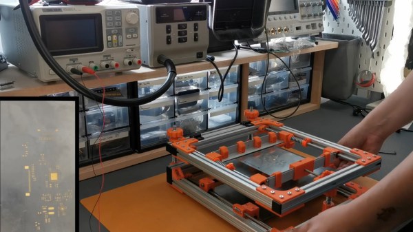
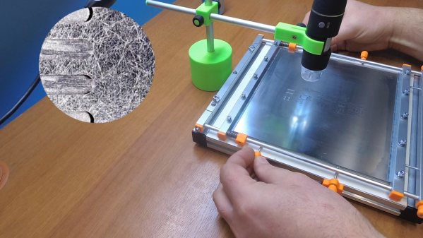
Luckily, [Valera Perinski] has come up with a better way to deal with stencils. The Stencil Printer is a flexible, adjustable alignment jig that reduces the amount of tedious adjustment needed to get things just so. The jig is built mostly from aluminum extrusions and 3D-printed parts, along with a bunch of off-the-shelf hardware. The mechanism has a hinged frame that holds the stencil in a fixed position above a platen, upon which rests the target PCB. The board is held in place by clamps that ride on threaded rods; with the stencil flipped down over the board, the user can finely adjust the relative positions of the board and the stencil, resulting in perfect alignment. The video below is mainly a construction montage, but if you skip to about the 29:00 mark, you’ll see the jig put through its paces.

Granted, such a tool is a lot more work than tape and spare PCBs, but if you do a lot of SMD work, it may be worth the effort. It’s certainly less effort than a solder-paste dispensing robot.

Continue reading “Adjustable Jig Eases PCB Stencil Alignment Process”

Matrix Of Resistors Forms The Hot Hands Behind This Thermochromic Analog Clock

If you’re going to ditch work, you might as well go big. A 1,024-pixel thermochromic analog clock is probably on the high side of what most people would try, but apparently [Daniel Valuch] really didn’t want to go to work that day.

The idea here is simple: heat up a resistor by putting some current through it, lay a bit of thermochromic film over it, and you’ve got one pixel. The next part was not so simple: expanding that single pixel to a 32 by 32 matrix.

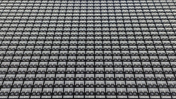
To make each pixel square-ish, [Daniel] chose to pair up the 220-ohm SMD resistors for a whopping 2,048 components. Adding to the complexity was the choice to drive them with a 1,024-bit shift register made from discrete 74LVC1G175 flip flops. With the Arduino Nano and all the other support components, that’s over 3,000 devices with the potential to draw 50 amps, were someone to be foolish or unlucky enough to turn on every pixel at once. Luckily, [Daniel] chose to emulate an analog clock here; that led to additional problems, like dealing with cool-down lag in the thermochromic film when animating the hands, which had to be dealt with in software.

We’ve seen other thermochromic displays before, including recently with this temperature and humidity display. This one may not be the highest resolution display out there, but it’s big and bold and slightly dangerous, and that makes it a win in our book.

Printable, Castable Feeders Simplify Pick-and-Place Component Management

It goes without saying that we love to see all the clever ways people have come up with to populate their printed circuit boards, especially the automated solutions. The idea of manually picking and placing nearly-microscopic components is reason enough to add a pick and place to the shop, but that usually leaves the problem of feeding components to the imagination of the user. And this mass-production-ready passive component feeder is a great example of that kind of imagination.

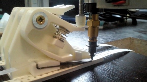
Almost every design we’ve seen for homebrew PnP component feeders have one of two things in common: they’re 3D-printed, or they’re somewhat complex. Not that those are bad things, but they do raise issues. Printing enough feeders for even a moderately large project would take forever, and the more motors and sensors a feeder has, the greater the chance of a breakdown. [dining-philosopher] solved both these problems with a simple design using only two parts, which can be resin cast. A lever arm is depressed by a plunger that’s attached to the LitePlacer tool, offset just enough so that the suction cup is lined up with the component location on the tape. A pawl in the lower arm moves forward when the tool leaves after picking up the part, engaging with the tape sprocket holes and advancing to the next component.

[dining-philosopher] didn’t attack the cover film peeling problem in his version, choosing to peel it off manually and use a weight to keep it taut and expose the next component. But in a nice example of collaboration, [Jed Smith] added an automatic film peeler to the original design. It complicates things a bit, but the peeler is powered by the advancing tape, so it’s probably worth it.

Continue reading “Printable, Castable Feeders Simplify Pick-and-Place Component Management”

A Ploopy Pick And Place

A fair number of hackers reach that awkward age in their careers – too old for manual pick and place, but too young for a full-fledged PnP machine. The obvious solution is to build your own PnP, which can be as simple as putting a suction cup on the Z-axis of an old 3D-printer. Feeding parts into the pick and place, though, can be a thorny problem.

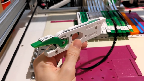
Or not, if you think your way through it like [Phil Lam] did and build these semi-automated SMD tape feeders. Built for 8-mm plastic or paper tapes, the feeders are 3D-printed assemblies that fit into a rack that’s just inside the work envelope of a pick and place machine. Each feeder has a slot in the top for the tape, which is advanced by using the Z-axis of the PnP to depress a lever on the front of the case. A long tongue in the tape slot gradually peels back the tape’s cover to expose a part, which is then picked up by the PnP suction cup. Any machine should work; [Phil] uses his with a LitePlacer. We like the idea that parts stay protected until they’re needed; the satisfyingly clicky lever action is pretty cool too. See it briefly in action in the video below.

It looks like [Phil] built this in support of his popular Ploopy trackball, which is available both as a kit and fully assembled. We think the feeder design is great whether you’re using PnP or not, although here’s a simpler cassette design for purely manual SMD work.

Continue reading “A Ploopy Pick And Place”

Supercon SMD Challenge Gets 3D Printed Probes: Build Your Own

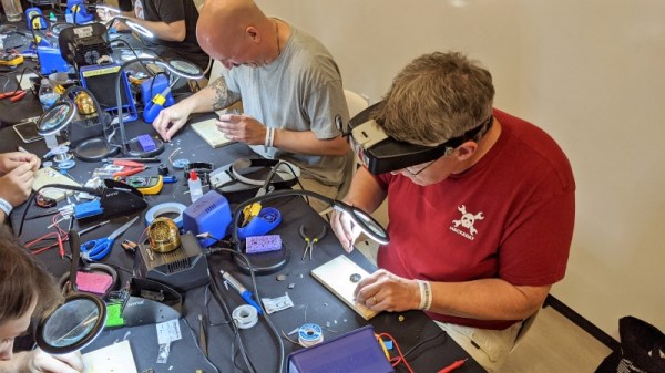
This year was the second SMD challenge at Supercon, so it stands to reason we probably learned a few things from last year. If you aren’t familiar with the challenge, you are served some pretty conventional tools and have to solder a board with LEDs getting progressively smaller until you get to 0201 components. Those are challenging even with proper tools, but a surprising number of people have managed to build them even using the clunky, large irons we provide.

During the first challenge, we did find one problem though. The LEDs are all marked for polarity. However, since we don’t provide super high power magnification, it was often difficult to determine the polarity, especially on the smaller parts. Last year, [xBeau] produced some quick LED testers to help overcome this problem. This year we refined them a bit.

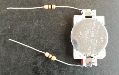
As you can see, the 2018 model was a very clever use of what was on hand. A CR2032 holder powered the probes and the probes themselves were two resistors. If you can get the LED to light with the probes you know which lead is the anode and which is the cathode. A little red ink makes it even more obvious. Continue reading “Supercon SMD Challenge Gets 3D Printed Probes: Build Your Own”

Creating Easy Glass Circuit Boards At Home

This tip for creating glass substrate circuit boards at home might hew a bit closer to arts and crafts than the traditional Hackaday post, but the final results of the method demonstrated by [Heliox] in her recent video are simply too gorgeous to ignore. The video is in French, but between YouTube’s attempted automatic translation and the formidable mental powers of our beloved readers, we don’t think it will be too hard for you to follow along after the break.

The short version is that [Heliox] loads her Silhouette Cameo, a computer-controlled cutting machine generally used for paper and vinyl, with a thin sheet of copper adhered to a backing sheet to give it some mechanical strength. With the cutting pressure of the Cameo dialed back, the circuit is cut out of the copper but not the sheet underneath, and the excess can be carefully peeled away.

Using transfer paper, [Heliox] then lifts the copper traces off the sheet and sticks them down to a cut piece of glass. Once it’s been smoothed out and pushed down, she pulls the transfer paper off and the copper is left behind.

From there, it’s just a matter of soldering on the SMD components. To make it a little safer to handle she wet sands the edges of the glass to round them off, but it’s still glass, so we wouldn’t recommend this construction for anything heavy duty. While it might not be the ideal choice for your next build, it certainly does looks fantastic when mounted in a stand and blinking away like [Heliox] shows off at the end.

Ironically, when compared to some of the other methods of making professional looking PCBs at home that we’ve seen over the years, this one might actually be one of the easiest. Who knew?

Continue reading “Creating Easy Glass Circuit Boards At Home”

A Newbie Takes The SMD Challenge At Supercon

First-time visitors to Disneyworld often naively think they’re going to “do” the park in three days: one day for the Magic Kingdom, one day for Epcot, and one day for everything else. It’s easy to spot such people, collapsed on a bench or dragging exhausted kids around while trying to make their way to the next must-see attraction. Supercon is something like that — a Disney-esque theme park for hackers that will exhaust you if you don’t have a plan, and if you don’t set reasonable expectations. Which is why I was glad that I set only one real goal for my first Supercon: take the SMD Soldering Challenge.

Now, while I’m pretty handy with a soldering iron, I was under no illusion that I would be at all competitive. All my soldering experience has been with through-hole components, and while I also used to doing some production soldering on fine-pitch connectors, the whole surface-mount thing is new to me. I entered mainly because I wanted to see what was possible coming in raw. At best I’d learn what my limits are, and at worst I’d fail spectacularly and provide grist for a “Fail of the Supercon” post. It’s a win either way.

Continue reading “A Newbie Takes The SMD Challenge At Supercon”