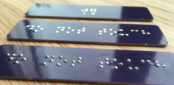
[jg] recently passed some damaged Braille signs and took on the challenge of repairing them. Informed by his recent work on PCB lapel pins, [jg] immediately thought of using circuit boards for this project. He’d noticed that round solder pads made for uniform hills of solder, and this reminded him of the bumps in Braille.
He began by reading up on the standards of the Braille Authority of North America, which stipulates a dot height of 0.6mm. He loaded up the PharmaBraille font system and laid it out the dots in photoshop, then and imported it into KiCad and laid out the boards. When the PCBs had arrived from OSH Park, [jg] soldering up the pads (lead free, but of course) to see if he could get the hills to 0.6mm. He’s experimenting with different methods of melting the solder to try to get more even results.
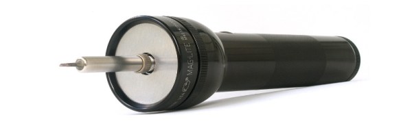
[David Schneider]’s love affair with Weller temperature controlled soldering irons began many years ago, but when he came to the point of needing a cordless iron he had problems finding one that replicated his trusty mains-powered soldering station. His solution was simple, to build his own, and in a stroke of genius he did so with an odd combination of a Weller MagnaStat element and bit, and a repurposed MagLite flashlight.
The Weller parts are all available off-the-shelf as spares, and the MagLite was easy to source. But its D cells would never give the required 24 V for the iron, so he had to incorporate a set of 14500 Li-ion cells with built-in electronic protection. The element protrudes from the front of the flashlight, giving an iron that seems to do the business but to our eyes looks rather unwieldy. Still, it does the job, and provides a far more sturdy and reliable iron than any cordless one we’ve yet seen, so we think that’s a result.
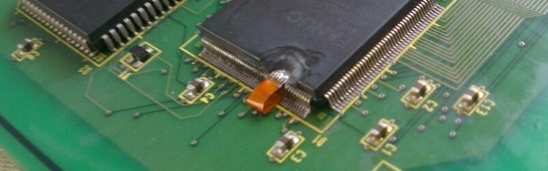
There’s no description of the incident that resulted in the pins of the QFP chip being ablated, but it looks like a physical insult like a tool dropped on the pins. [rasminoj]’s repair consisted of carefully grinding away the epoxy cap to expose the internal traces leading away from the die and soldering a flexible cable with the same pitch between the die and the PCB pads.
This isn’t just about [rasminoj]’s next-level soldering skills, although we’ll admit you’ve got to be pretty handy with a Hakko to get the results shown here. What we’re impressed with is the wherewithal to attempt a repair that requires digging into the chip casing in the first place. Most service techs would order a new board, or at best solder in a new chip. But given that the chip sports a Fanuc logo, our bet is that it’s a custom chip that would be unreasonably expensive to replace, if it’s even still in production. Where there’s a skill, there’s a way.
In unlocking the extra performance, he takes readers through a primer on the device tree, and is happy to report that his transfer rate has increased from 26 to 36 MB/s, a tidy return on his work.
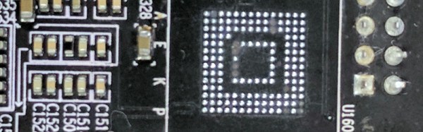
However, the story doesn’t end there. The 8GB Samsung eMMC chip wasn’t quite as roomy as he’d have liked, so it was time to replace it with a 32GB version. Even with careful desoldering, he managed to lift a few pads, though very fortunately they were ones that were either NC or power rails that were duplicated elsewhere. Some tricky reflowing of what is quite a formidable BGA package to do by hand, and he was rewarded with a working board featuring higher flash capacity. We salute him for taking it on, we probably wouldn’t have had the courage.
[Joshua] has frequent discussions about his soldering techniques with viewers of his YouTube channel. He finally decided to interview [Randy Rubinstein] who is the president of SRA Soldering. In nearly an hour, they talk about everything from solder alloys to proper temperature. They also talk about lead exposure, flux cleaning, and lead-free solder.
They also talk about strategies for rework with lead-free and using special solder for removing SMD components. Honestly, although the first frame of the video says “your solder sucks,” we didn’t really find any earth-shattering revelations about something everyone’s doing wrong. We did, however, find a lot of good advice and some interesting details about things like the uses for different solder alloys.
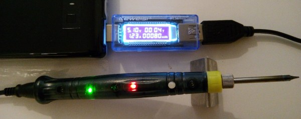
You’ve surely seen the TS-100 soldering iron. It has an OLED display, an ARM processor, and will run with an external battery pack. They are not too pricey, but at $80 or so they aren’t exactly an impulse buy, either. [Drone Camps RC] used one in the field and decided to try a Hakko FX-901 instead. He did a video review that you can see below.
The FX-901 is about half the price of a TS-100. Granted, it doesn’t have a fancy display and you can’t hack it to play Tetris. However, it does take batteries (including rechargeable) without an external pack. The manufacturer claims up to two hours of use and that it will melt solder in 40 seconds. From the video, the iron actually melted solder in under 30 seconds. The two hours, by the way, is with rechargeables. Alkaline AA batteries should give about 70 minutes of operation.
So I made an awful, kludgey, “there I fixed it” level repair, and I need to come clean. This is really a case of an ill-advised ground.
My thirteen-year-old daughter asked for help repairing her Macbook charging cable. Macbook chargers really aren’t meant to flex around a lot, and if you’re the kind of person who uses the laptop on, well, the lap, with the charger in, it’s gonna flex. Sooner or later the insulation around the plug housing, where it plugs into the laptop, cracks and the strands of wire can be seen. This type of cable consists of an insulated lead wire surrounded by a stranded ground wire. The problem with this configuration is that the stranded ground also gets flexed until it breaks, one strand at a time, until the cable stops working.
So it was with my daughter’s Macbook cable. I didn’t have the money to buy her a new one, and I figured we could repair the break. We busted out her WLC100 and sat down to get our solder on. She started off working while I supervised, then I took over later on.
We began by using an Xacto to cut away enough insulation to expose about half an inch of the stranded wire. We pulled the wire away from the insulated lead wire and twisted it into a single stranded wire parallel to the lead wire. Grabbing for the iron, we tinned the ground and soldered a length of 22-gauge solid wire to it. The way the ground connects to the plug is by passing through a conductive ring. My idea was to solder the other end of the 22-gauge wire to the metal ring. Here’s where things started to go wrong. This is, by the way, the part where I took over so you can blame me and not my kid.
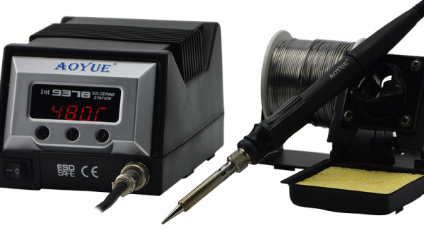
My daughter was using the WLC100’s default tip. I should have grabbed my own iron, a WES51, or at least swapped in its ninja-sharp tip. The WLC100’s default tip is a big fat wedge and it was too big to put next to the plug, and the conductive ring quickly got covered in melted plastic and I couldn’t solder anything to it. Worse, I had accidentally burned through the insulation protecting the lead wire, and had to cover it in electrical tape.
What now? We were left with not being able to use the cable at all. One option was to wait until the goop had cooled and burnish it clean with a Dremel, then attempt to re-solder using an appropriate tip. However, that sounded like a lot of work. The solid wire was still securely soldered to the ground, so instead of trying to attach it to the cable side of the plug, I could connect it to the computer side, by shoving it into the socket alongside the plug. The business end of the plug has a big silver ground surrounding small gold positive leads, and touching the ground with the wire should work just fine, right?
It did. The computer charged up as happy as you’d like. And yet, I was left with the distinct feeling the solution could have been, I don’t know, cleaner. Certainly, the iFixit route shown here comes out much cleaner by sliding off the housing, clipping the damaged wire, and beginning anew. Clean as this is, it’s just waiting to happen the same way again.
So, brethren and sistren, lay on with brickbats and tell what I did wrong. What approaches have you used to fix cables broken where they meet the plug housing, and how do you improve the situation for the future?