When you’re debugging two bits of electronics talking SPI to each other, there’s a lot that can go sideways. Starting from the ground up, the signals can be wrong: data not synced with clocks right, or phase inverted. On top of that, the actual data sent needs to make sense to the receiving device. Are you sending the right commands?
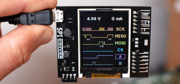
When nothing’s working, you’re fighting simultaneously on these two fronts and you might need different tools to debug each. An oscilloscope works great at the physical layer, while something like a Bus Pirate or fancier logic analyzer works better at the data layer because it can do parsing for you. [James Bowman]’s SPIDriver looks to us like a Bus Pirate with a screen — giving you a fighting chance on both fronts.
 SPIDriver also has a couple more tricks up its sleeve: a voltage and current monitor for the device under test, so you don’t even have to break out your multimeter when you’re experiencing random resets. We asked [James] if these additions had a sad history behind them. He included this XKCD.
Everything about SPIDriver is open, so you can check out the hardware design, browse the code, and modify any and all of it to your taste. And speaking of open, [James] is also the man behind the Gameduino and an amazing FPGA Forth soft-CPU.
It’s fully crowd-funded, but it closes in a couple of days so if you want one, get on it soon.
And if you want to learn more about SPI debugging, we’ve written up a crash-course. With the gear and the know-how, you at least stand a fighting chance.

