Q Meter Measures… Q, Of Course

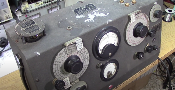
If you’ve ever dealt with RF circuits, you probably have run into Q — a dimensionless number that indicates the ratio of reactance to resistance. If you ever wanted to measure Q, you could do worse than pick up a vintage Boonton 160A Q meter. [Mikrowave1] did just that and shows us how it works in the video below.

Most often, the Q is of interest in an inductor. A perfect inductor would have zero resistance and be all reactance. If you could find one of those, it would have an infinite Q because you divide the reactance by the resistance. Of course, those inductors don’t exist. You can also apply Q to any circuit with reactance and the video talks about how to interpret Q for tuned circuits. You can also think of the Q number as the ratio of frequency to bandwidth or the dampening in an oscillator. A versatile measurement, indeed.

It sounds as though you could just measure the resistance of a coil and use that to compute Q. But you really need to know the total loss, and that’s not all due to resistance. A meter like the 160A uses a signal generator and measures the loss through the circuit.

The best part of the video is the teardown, though. This old tube gear is oddly beautiful in a strange sort of way. A real contrast to the miniaturized circuits of today. The Q meter is one of those nearly forgotten pieces of gear, like a grid dip oscillator. If you need to wind your own coils, by the way, you could do worse than see how [JohnAudioTech] does it.

Continue reading “Q Meter Measures… Q, Of Course”

A Handy OSHW USB Cable Tester For Your Toolkit

There’s no shame in admitting you’ve been burned by a cheapo USB cable — ever since some bean counter realized there was a few cents to be saved by producing “power only” USB cables, no hardware hacker has been safe. But with this simple tester from [Álvaro Prieto] in your arsenal, you’ll never be fooled again.

It’s about as straight-forward a design as possible, utilizing nothing more than a two dozen LEDs, their associated resistors, and a common CR2032 coin cell. Simply plugging both sides of your cable into the various flavors of USB connectors on the tester will complete the necessary circuits to light up the corresponding LEDs, instantly telling you how many intact wires are inside the cable. So whether you’re dealing with some shady cable that doesn’t have the full complement of conductors, or there’s some physical damage that’s severed a connection or two, you’ll know at a glance.

A sage warning for most of the devices we build.

Obviously the tester is designed primarily for the 24 pins you’ll find in a proper USB-C connector, but it’s completely backwards compatible with older cables and connectors. We appreciate that he even included the chunky Type B connector, which we’ve always been fond of thanks to its robustness compared to the more common Mini and Micro variants.

Keep in mind though that this tester will only show you if there’s a connection between two pins, it won’t verify how much power it can actually handle. For that, you’ll need some extra equipment.

Better Scope Measurements

There was a time when few hobbyists had an oscilloscope and the ones you did see were old military or industrial surplus that were past their prime. Today you can buy a fancy scope for about what those used scopes cost that would have once been the envy of every giant research lab. However, this new breed of instrument is typically digital and while they look like an old analog scope, the way they work leads to some odd gotchas that [Arthur Pini] covers in a recent post.

Some of his tips are common sense, but easy to forget about. For example, if you stack your four input channels so each uses up a quarter of the screen, it makes sense, right? But [Arthur] points out that you are dropping two bits of dynamic range, which can really jack up a sensitive measurement.

Continue reading “Better Scope Measurements”

Frequency Counter Restoration Impeded By Kittens

We think of digital displays as something you see on relatively modern gear. But some old gear had things like nixies or numitrons to get cool-looking retro digital displays. The HP 521A frequency counter, though, uses four columns of ten discrete neon bulbs to make a decidedly low-tech but effective digital display. [Usagi Electric] has been restoring one of these for some time, but there was a gap between the second and third videos as his workshop became a kitten nursery. You can see the last video below.

In previous videos, he had most of the device working, but there were still some odd behavior. This video shows the final steps to success. One thing that was interesting  is that since each of the four columns are identical, it was possible to compare readings from one decade to another.

However, in the end, it turned out that the neon bulbs were highly corroded, and replacing all the neon bulbs made things work better. However, the self-check that should read the 60 Hz line frequency was reading 72 Hz, so it needed a realignment. But that was relatively easy with a pot accessible from the back panel. If you want to see more details about the repair, be sure to check out the earlier videos.

We love this old gear and how clever designers did so much with what we consider so little. We hate to encourage your potential addiction, but we’ve given advice on how to acquire old gear before. If you want to see what was possible before WS2812 panels, you could build this neon bulb contraption.

Continue reading “Frequency Counter Restoration Impeded By Kittens”

Mapping Out The LEDs On An Outlet Tester

The concept of an outlet tester is pretty simple: plug the gadget into a suspect wall receptacle, and an array of LEDs light up in various patterns to alert the user to any wiring faults. They’re cheap, reliable, and instantaneous. Most people wouldn’t give them much more thought than that, but like any good hacker, [Yeo Kheng Meng] wanted to know how these devices worked.

After picking up a relatively advanced model that featured an LCD display capable of showing various stats such as detected voltage in addition to the standard trio of LEDs, he started by using some test leads to simulate various fault conditions to understand the basic principle behind its operation. The next step was to disassemble the unit, which is where things went briefly sideways — it wasn’t until [Yeo Kheng Meng] and a friend had nearly cut through the enclosure that they realized it wasn’t ultrasonically welded liked they assumed, and that the screws holding it together were actually hidden under a sticker. Oops.

The write-up includes some excellent PCB shots, and [Yeo Kheng Meng] was able to identify several components and ascertain their function. He was even able to find some datasheets, which isn’t always such an easy task with these low-cost devices. Unfortunately the MCU that controls the device’s more advanced features is locked away with a black epoxy blob, but he was able to come up with a schematic that explains the rather elegant logic behind the LED display.

This isn’t the first time [Yeo Kheng Meng] has taken apart an interesting piece of hardware for our viewing pleasure, and given the fine job he does of it, we hope it’s not the last either.

Homebrew Curve Tracer Competes With The Big Guns

When we first saw the VBA curve tracer, we thought it might have something to do with Visual Basic for Applications. But it turns out it is a mash up of the names of the creators: [Paul Versteeg], [Bud Bennett], and [Mark Allie]. [Paul] designed an original prototype back in 2017. Since then, the project has grown and lessons were learned. The final curve tracer is pretty impressive in more ways than one.

If you’ve never used a curve tracer, they allow you to characterize components using their characteristic curve of voltage versus current. You use an oscilloscope as an output device. This instrument is often used by engineers trying to understand or match devices like diodes, transistors, or — in some cases — even tubes. So if you want to measure the collector-emitter breakdown voltage, for example, or the collector cutoff current, this is your go-to device. You can also match gains in circuits where that matters (for example, a push-pull circuit where two transistors amplify different parts of the same signal).

If you want to understand more about how it works, there are a series of blog posts covering the evolution of the device. You can also find the design files on GitHub. There is also a handy post showing many types of measurements you might want to make.

This is a good-looking project. We’ve seen it done on the cheap, but slowly. Or spend $15 and do better. We doubt any of these have high enough voltages to do most tubes, but they made the same basic instrument for tubes back in the 1950s.

Resulting tweezer assembly, with a 3D printed replacement case for both of the probes

Hackaday Prize 2022: Glue-Hindered Smart Tweezer Repair Involves A Rebuild

[Dan Julio] owns a pair of Miniware multimeter tweezers, a nifty helper tool for all things SMD exploration. One day, he found them broken – unable to recognize any component between the two probes. He thought it could be a broken connection problem, and decided to take them apart. Presence of some screws on their case fooled him – in the end, it turned out that the case was glued together, and could only be opened destructively. For an entry in the “Reuse, Recycle, Revamp” round of 2022 Hackaday Prize, he tells us how he brought these tweezers back from the dead.

During the disassembly, he broke a custom flexible PCB, which wasn’t reassuring either. However, that was no reason to give up – he reverse-engineered the connections and the charging circuitry, then assembled parts of the broken tweezers together using a small generic protoboard as a base. Indeed, it was likely a broken connection between probes, because the reassembled tweezers worked!

Of course, having exposed PCBs wouldn’t do, and from the very start, assembling these tweezers back together was not an option. Instead, he developed a replacement case in OpenSCAD, bringing the tweezers back to life as his trusty tool – and still leaving repairability on the table. If you’re interested in the details, he goes more into how these tweezers are designed when it comes to charging and connectivity, and we recommend that you give his write-up a read!

We’ve been seeing smart tweezers around for over a decade now, from reviews and hacks of commercially made ones, to DIY chopstick-based and PCB-based ones. If you already own a pair of tweezers you’ve grown attached to, you can neatly retrofit them with a capacitance sensing function!