Motor Test Bench Talks The Torque

Salvaging a beefy motor is one life’s greatest pleasures for a hacker, but, when it comes to using it in a new project, the lack of specs and documentation can be frustrating. [The Post Apocalyptic Inventor] has a seemingly endless stockpile of scavenged motors, and decided to do something about the problem.

Once again applying his talent for junk revival, [TPAI] has spent the last year collecting, reverse-engineering and repairing equipment built in the 1970s, to produce a complete electric motor test setup. Parameters such as stall torque, speed under no load, peak power, and more can all easily be found by use of the restored test equipment. Key operating graphs that would normally only be available in a datasheet can also be produced.

The test setup comprises of a number of magnetic particle brakes, combined power supply and control units, a trio of colossal three-phase dummy loads, and a gorgeously vintage power-factor meter.

Motors are coupled via a piece of rubber to a magnetic particle brake. The rubber contains six magnets spaced around its edge, which, combined with a hall sensor,  are used to calculate the motor’s rotational speed. When power is applied to the coil inside the brake, the now magnetised internal powder causes friction between the rotor and the stator, proportional to the current through the coil. In addition to this, the brake can also measure the torque that’s being applied to the motor shaft, which allows the control units to regulate the brake either by speed or torque. An Arduino slurps data from these control units, allowing characteristics to be easily graphed.

If you’re looking for more dynamometer action, last year we featured this neatly designed unit – made by some Cornell students with an impressive level of documentation.

Continue reading “Motor Test Bench Talks The Torque”

MacGyvering Test Lead Clips

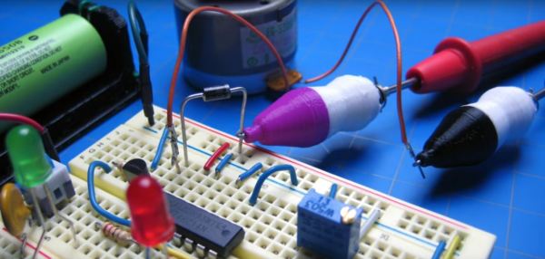
Okay fellow Make-Gyvers, what do you get when you cross a peripheral power cable jumper, a paperclip, springs, and some 3D-printed housings? DIY test lead clips.

Test clips are easily acquired, but where’s the fun in that? [notionSuday] started by removing the lead connectors from the jumper, soldering them to stripped lengths of paperclip, bent tabs off the connectors to act as stoppers, and slid springs over top. Four quick prints for the housings later, the paperclip assembly fit right inside, the tips bent and clipped to work as the makeshift clamp. Once slipped onto the ends of their multimeter probes, they worked like a charm.

Continue reading “MacGyvering Test Lead Clips”

Awesome Prank Or Circuit-Breaker Tester?

Many tools can be used either for good or for evil — it just depends on the person flipping the switch. (And their current level of mischievousness.) We’re giving [Callan] the benefit of the doubt here and assuming that he built his remote-controlled Residual Current Device (RDC) tripper for the purpose of testing the safety of the wiring in his own home. On the other hand, he does mention using it to shut off all the power in his house during an “unrelated countdown at a party”. See? Good and evil.

An RCD (or GFCI in the States) is a kind of circuit breaker that trips when the amount of current in the hot and neutral mains power lines aren’t equal and opposite, which would suggest that the juice was leaking out somewhere, hopefully not through someone. They only take a few milliamps of imbalance to blow so that nobody gets hurt. Making a device to test an RCD is easy; a resistor between hot and the protective ground circuit would do.

[Callan] over-engineers. He used a 50 W resistor where 30 W would do under the worst circumstances. A stealthy solid-state relay switches the resistor in, driven by an Uno and a Bluetooth module, so he can trip his circuit breakers from his smartphone, naturally.
Continue reading “Awesome Prank Or Circuit-Breaker Tester?”

Drone Vs. Airplane? Who Will Win? Science Knows.

Ignore the article, watch the video at the top of the page. The article is about some idiot, likely not even a hacker, who bought a drone somewhere and nearly rammed it into a plane. He managed this with concentrated idiocy, intention was not involved. While these idiots are working hard to get our cool toys taken away, researchers elsewhere are answering the question of exactly how much threat a drone poses to an airplane.

droneexplode_thumbAirplanes are apparently armored to withstand a strike from an 8lb bird. However, even if in a similar weight class, a drone is not constructed of the same stuff. To understand if this mattered, step one was to exactly model a DJI Phantom and then digitally launch it at various sections of a very expensive airplane.

The next step, apparently, was to put a drone into an air cannon and launch it at an aluminum sheet. The drone explodes quite dramatically. Some people have the best jobs.

The study is still ongoing, but from the little clips seen; the drone loses. Along with the rest of us.

Perhaps the larger problem to think about right now is how to establish if a “drone” has actually been involved in an incident with a passenger aircraft. It seems there are a lot of instances where that claim is dubious.

Think You Know C? Find Out

I’ve had the fortune or misfortune of interviewing a lot of job candidates over the years. It amazes me how often someone will claim to know something, sound reasonable, but then if you quiz them on it, it becomes really obvious that they don’t know much. To flush this out, we had a three-question test that would tell you a lot. People who got the right answer were ahead of the game, of course, but even looking at how people approached the answer (right or wrong) would tell you a lot, too.

I remember one case where the answer involved casting a value. A candidate had impressed me until faced with the question to which he said (more or less): “Well, there’s this function. I think it is called ‘cast’…” I think the look on my face told him that I actually knew the answer (not surprising, since I was giving the test) and that wasn’t it.

[Oleksandr Kaleniuk] has a C quiz of only five simple questions. They reminded me of at least one of my old company’s three-question quiz. I don’t want to say too much about the character of the test because I don’t want to give away the answers, but if you think you are a C wizard, go check it out. Then come back in the comments and tell us how you did. Just try to avoid posting spoilers (although you should probably avoid the comment section until you come back).

Continue reading “Think You Know C? Find Out”

Bring Doping, Microfluidics, Photovoltaics, And More Into The Home

Can you make a spectrometer for your home lab all from materials you have sitting around? We might not believe it from a less credible source, but this MIT course does indeed build a spectrometer from foam board using two razor blades as the silt cover and a writable CD as the diffraction grating. The coolest part is removing the metal backing of the CD.

mit_experiments_thumbHackaday reader [gratian] tipped us off about the course available from MIT courseware called Nanomaker. It boils down some fairly complicated experiments to the kind one can do in the home lab without involving thousands of dollars of lab equipment. The whole point is to demystify what we think of as complicated devices and topics surrounding photovoltaics, organic photovoltaics, piezoelectricity and thermoelectricity.


Spectrometers are used to analyze the wavelengths of a light source. Now that you have a measurement tool in hand it’s time to build and experiment with some light sources of your own. Here you can see an LED that is the topic of one of the course labs.

If you have a bit of background in chemistry this is a good step-by-step guide for getting into these types of experiments at home. It reminds us of some of the really cool stuff [Jeri Ellsworth] was doing in her garage lab, like making her own EL panels.

Continue reading “Bring Doping, Microfluidics, Photovoltaics, And More Into The Home”

Super In-Depth $15 Curve Tracer Project

[Jason Jones] has always wanted a curve tracer for his home shop. When he was starting out in electronics he fell in love with a machine called a Huntron Tracker 2000. This machine would feed a sine wave into a circuit on one side and plot a XY graph on the other.

[Jason] figured that with a modern microcontroller such a device could be build simply and cheaply for around $15 dollars. With that requirement in mind he set out to build it. He selected a PIC24F16KM202 for the brain and got to work.

The write-up is really great. It’s rare that someone puts every step of their development and design thinking into writing. Some have argued that this is the only true way to have an OSHW hardware project. The series covers everything from the initial requirements and parts selection to the software development and eventual testing of the device.

[Jason] managed to build a pretty capable little curve tracer in the end. We really enjoyed it when he used the tracer to debug the tracer.