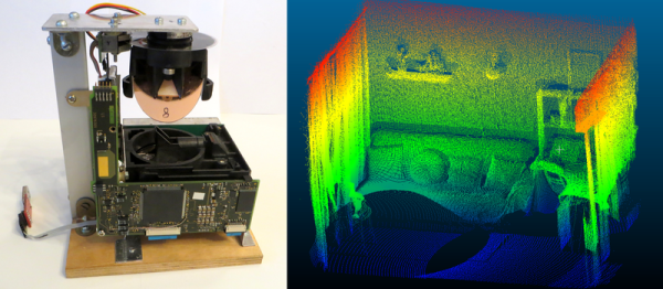
For any project there’s typically a trade-off between quality and cost,as higher quality parts, more features, or any number of aspects of a project can drive its price up. It seems as though [iliasam] has managed to avoid this paradigm entirely with his project. His new LIDAR system knocks it out of the park on accuracy, sampling, and quality, and somehow manages to only cost around $114 in parts.
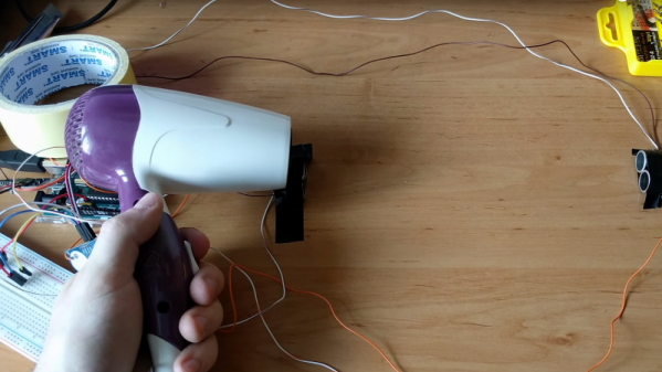
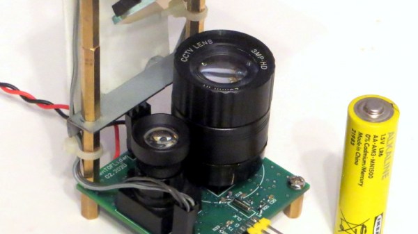
A LIDAR system works by sending out many pulses of light in different directions, measuring the reflections of that light as it returns. LIDAR systems therefore improve with higher frequency pulses and faster control electronics for both the laser output and the receiving data. This system manages to be accurate to within a few centimeters and works up to 25 meters all while operating at 15 scans per second. The key was a high-powered laser module which can output up to 75 watts for extremely short times. More details can be found at this page (Google Translate from Russian).
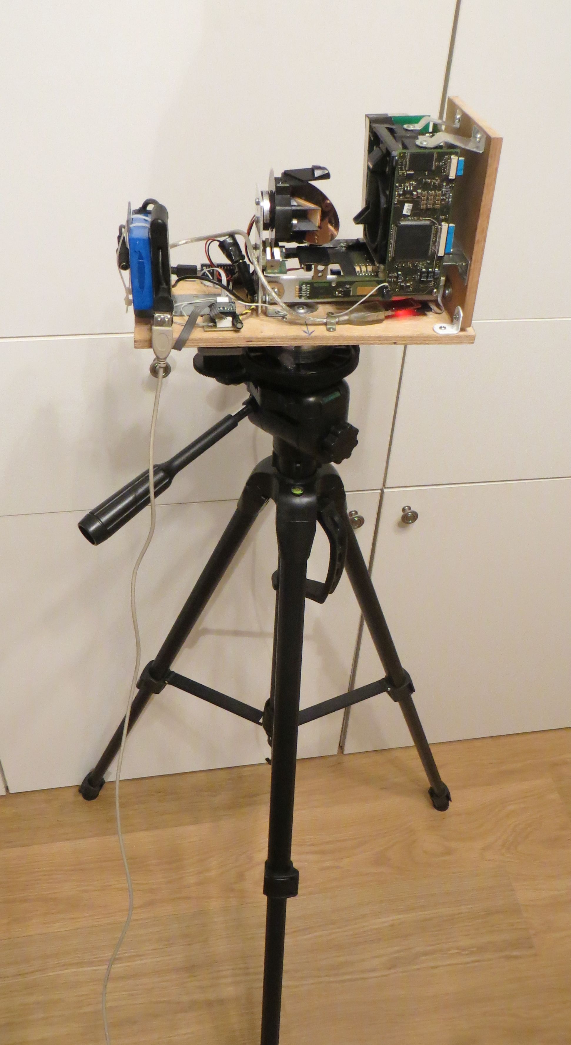
Another bonus from this project is that [iliasam] has made everything available from his GitHub page including hardware specifications, so as long as you have a 3D printer this won’t take long to produce either. There’s even detailed breakdowns of how the laser driving circuitry works, and how there are safety features built in to keep anyone’s vision from accidentally getting damaged. Needless to say, this isn’t just a laser rangefinder module but if you want to see how you can repurpose those, [iliasam] can show you that as well.