Internal Combustion Torque Monster Has Great Impact

Once the domain of automotive repair shops and serious hobbyists with air compressors, the impact driver so famously used to remove and install wheel lug nuts and other Big Fasteners with just a squeeze of the trigger is more accessible than ever. Thanks to Lithium Ion batteries and powerful and compact brushless motors, you can now buy a reasonably powerful and torquey impact driver for a relatively low price- no air compressor needed! But what if you relish the thought of a noisy, unwieldy and unnecessarily loud torque monster? Then the video below the break by [Torque Test Channel] is just what you need!

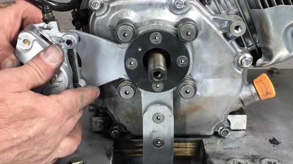
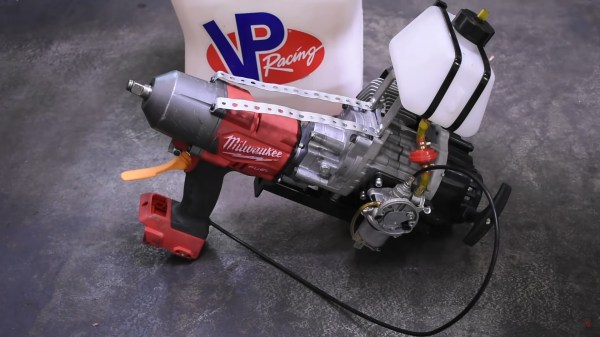
Now, this is Hackaday, so we don’t have to go into detail about why a person might want to rip out the electric motor and adapt a 60cc 2 stroke engine in its place. Of course that’s the obvious choice. But [Torque Test Channel] isn’t just mucking about for the fun of it. No, they’re having their fun, experimenting with internal combustion engines in odd places before they are banned by 2024 in California. Now, we’re not sure if the ban includes these exact types of engines- but who needs details when you have an impact driver that can change semi tires like a NASCAR pit crew.

Looking like an overpowered weapon from a first person shoot’em up game, [Torque Test Channel]’s modified Milwaukee tests well after some modifications. Be sure to watch the video to see how it performs against an electric tool that’s even larger than itself. There are graphs, charts, and an explanation of what can be done to make even more power in the future. We’re looking forward to it!

What’s that you say? You don’t have a two stroke engine sitting around waiting to be swapped into ridiculous gadgets? Look no further than your local fridge compressor and be ready to burn some hours getting it running.

Continue reading “Internal Combustion Torque Monster Has Great Impact”

Harmonic Drive Uses Compliant Mechanism To Slim Down

[Levi Janssen] has a secret: he doesn’t like harmonic drives. But rather than abandon the torque-amplifying transmission completely, he decided to see about improving them using 3D-printed compliant mechanisms.

For the uninitiated, harmonic drives, also known as strain-wave gears, are a compact, high-torque gearbox that has become popular with “robotic dog” makers and other roboticists. The idea is to have a rigid, internally-toothed outer ring nested around an externally-toothed, flexible cup. A wave generator rotates within the inside cup, stretching it so that it meshes with the outer ring. The two gears differ by only a couple of teeth, meaning that very high gear ratios can be achieved, which makes them great for the joints of robot legs.

[Levi]’s problem with the harmonic drive is that due to the depth of the flexible spline cup, compactness is not among its virtues. His idea is to couple the flex spline to the output of the drive through a flat spring, one that allows flexion as the wave generator rotates but transmits torque efficiently. The entire prototype is 3D-printed, except for the wave generator bearings and stepper motor, and put to the test.

As the video below shows after the excellent introduction to harmonic drives, the concept works, but it’s not without its limitations. Even lightly loaded, the drive made some unpleasant crunching sounds as the PLA springs gave out. We could easily see that being replaced with, say, a steel spring, either machined or cut on a water-jet machine. That might solve the most obvious problem and make [Levi]’s dream of a compact harmonic drive a reality. Of course, we have seen pretty compact strain-wave gears before.

Continue reading “Harmonic Drive Uses Compliant Mechanism To Slim Down”

This Custom Dynamometer Is A Stirling Example Of Homebrewing

[Leo Fernekes] has fallen down the Stirling engine rabbit hole. We mustn’t judge — things like this happen in the best of families, after all. And when they do happen to someone like [Leo], things can get interesting mighty quickly.

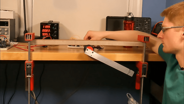
His current video, linked below, actually has precious little to do with his newfound Stirling engine habit per se. But when you build a Stirling engine, and you’re of a quantitative bent, having some way to measure its power output would be handy. That’s a job for a dynamometer, which [Leo] sets out to build in grand fashion. Dynos need to measure the torque and rotational speed of an engine while varying the load on it, and this one does it with style.

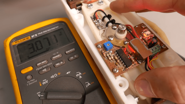
[Leo]’s torque transducer is completely DIY, consisting of hand-wound coils on the ends of a long lever arm that’s attached to the output shaft of the engine under test by a magnetic coupling. The coils are free to move within a strong magnetic field, with a PID loop controlling the current in the coils. Feedback on the arm’s position is provided by an optical sensor, also DIY, making the current necessary to keep the arm stationary proportional to the input torque. The video goes into great detail and has a lot of design and build tips.

We just love the whole vibe of this build. There may have been simpler or quicker ways to go about it, but [Leo] got this done with what he had on hand for a fraction of what buying in off-the-shelf parts would have cost. And the whole thing was a great learning experience, both for him and for us. It sort of reminds us of a dyno that [Jeremy Fielding] built a while back, albeit on a much different scale.

Continue reading “This Custom Dynamometer Is A Stirling Example Of Homebrewing”

Simple Demo Shows The Potential Of Magnetic Gears

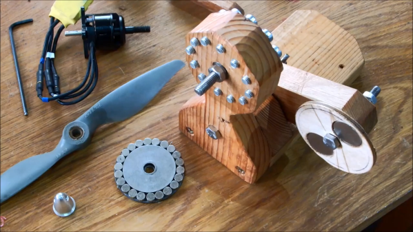
We’ve probably all used gears in our projects at one time or another, and even if we’re not familiar with the engineering details, the principles of transmitting torque through meshed teeth are pretty easy to understand. Magnetic gears, though, are a little less intuitive, which is why we appreciated stumbling upon this magnetic gear drivetrain demonstration project.

[William Fraser]’s demo may be simple, but it’s a great introduction to magnetic gearing. The stator is a block of wood with twelve bolts to act as pole pieces, closely spaced in a circle around a shaft. Both ends of the shaft have rotors, one with eleven pairs of neodymium magnets arranged in a circle with alternating polarity, and a pinion on the other side of the stator with a single pair of magnets. When the pinion is spun, the magnetic flux across the pole pieces forces the rotor to revolve in the opposite direction at a 12:1 ratio.

Watching the video below, it would be easy to assume such an arrangement would only work for low torque applications, but [William] demonstrated that the system could take a significant load before clutching out. That could even be a feature for some applications. We’ve got an “Ask Hackaday” article on magnetic gears if you want to dive a little deeper and see what these interesting mechanisms are good for.

Continue reading “Simple Demo Shows The Potential Of Magnetic Gears”

Can Lego Break Steel?

Betteridge’s Law of Headlines holds that any headline ending in a question mark can be answered with a resounding “No”. But as the video below shows, a Lego machine that twists steel asunder is not only possible, it’s an object lesson in metal fatigue. Touché, [Betteridge].

In pitting plastic against metal, the [Brick Experiment Channel] relied on earlier work with a machine that was able to twist a stock plastic axle from the Technics line of parts like a limp noodle. The steel axle in the current work, an aftermarket part that’s apparently no longer available, would not prove such an easy target.

Even after beefing up the test stand with extra Technics struts placed to be loaded in tension, and with gears doubled up and reinforced with extra pins, the single motor was unable to overcome the strength of the axle. It took a second motor and a complicated gear train to begin to deform the axle, but the steel eventually proved too much for the plastic to withstand. Round Two was a bit of a cheat: the same rig with a fresh axle, but this time the motor rotation was constantly switched. The accumulated metal fatigue started as a small crack which grew until the axle was twisted in two.

The [Brick Experiment Channel] is a fun one to check out, and we’ve featured them before. Along with destructive projects like this one, they’ve also got fun builds like this Lego playing card launcher, a Technic drone, and a Lego submarine.

Continue reading “Can Lego Break Steel?”

This DIY Dynamometer Shows Just What A Motor Can Do

Back in high school, all the serious gearheads used to brag about two things: their drag strip tickets, and their dynamometer reports. The former showed how fast their muscle car could cover a quarter-mile, while the latter was documentation on how much power their carefully crafted machine could deliver. What can I say; gas was cheap and we didn’t have the Internet to distract us.

Bragging rights are not exactly what [Jeremy Fielding] has in mind for his DIY dynamometer, nor is getting the particulars on a big Detroit V8 engine. Rather, he wants to characterize small- to medium-sized electric motors, with an eye toward repurposing them for different projects. To do this, he built a simple jig to measure the two parameters needed to calculate the power output of a motor: speed and torque. A magnetic tachometer does the job of measuring the motor’s speed, but torque proved a bit more challenging. The motor under test is coupled to a separate electric braking motor, which spins free when it’s not powered. A lever arm of known length connects to the braking motor on one end while bearing on a digital scale on the other. With the motor under test spun up, the braking motor is gradually powered, which rotates its housing and produces a force on the scale through the lever arm. A little math is all it takes for the mystery motor to reveal its secrets.

[Jeremy]’s videos are always instructional, and the joy he obviously feels at discovery is infectious, so we’re surprised to see that we haven’t featured any of his stuff before. We’ve seen our share of dynos before, though, from the tiny to the computerized to the kind that sometimes blows up.

Continue reading “This DIY Dynamometer Shows Just What A Motor Can Do”

Are You Getting Your Money’s Worth From Threaded Inserts?

Have you ever wondered whether it’s worth the time and expense to install threaded inserts into your 3D-printed projects? [Stefan] from CNC Kitchen did, and decided to answer the question once and for all, with science.

If this sounds familiar, it’s with good reason: we covered [Stefan]’s last stab at assessing threaded inserts back in March. Then, he was primarily interested in determining if threaded inserts are better than threads cut or printed directly into parts. The current work is concerned with the relative value of different designs of threaded inserts. He looked at three different styles of press-in inserts, ranging in price from pennies apiece to a princely 25 cents. The complexity of the outside knurling seems not to be correlated with the price; the inserts with opposed helical knurls seem like they’d be harder to manufacture than the ones with simple barbs on the outside of the barrel, but cost less. And in fact, the mid-price insert outperformed the expensive one in pull-out tests. Surprisingly, the cheapest inserts were actually far worse at pull-out resistance than printing undersized holes and threading an M3 screw directly into the plastic.

[Stefan] also looked at torque resistance, and found no substantial difference between the three insert types. Indeed, none of the inserts proved to be the weak point, as the failure mode of all the torque tests was the M3 bolt itself. This didn’t hold with the bolt threaded directly into the plastic, of course; any insert is better than none for torque resistance.

We enjoyed seeing [Stefan]’s tests, and appreciate the data that can help us be informed consumers. [John] over at Project Farm does similar head-to-head tests, like this test of different epoxy adhesives.

Continue reading “Are You Getting Your Money’s Worth From Threaded Inserts?”