Illuminated 3D Printed Guitar Is Ready To Rock

When we think of 3D printed parts for our projects, most of us imagine little bits like brackets and mounting plates. Perhaps the occasional printed project enclosure. But if you’ve got a big custom printer as [Joshendy] does, plus plenty of time, it opens up a whole new world of large scale projects. Take for example the gorgeous RGB LED guitar body he recently completed.

Despite the considerable 300 x 300 mm build area of his custom 3D printer, [Joshendy] still had to design the guitar body in sections that could be bolted together after being printed in ABS. It took around 60 hours to run off all the parts, with the large central section taking the longest to print at 28 hours. With the generous application of heat-set inserts, the assembled guitar should be plenty strong.

The white ABS of the guitar body helps diffuse the LEDs.

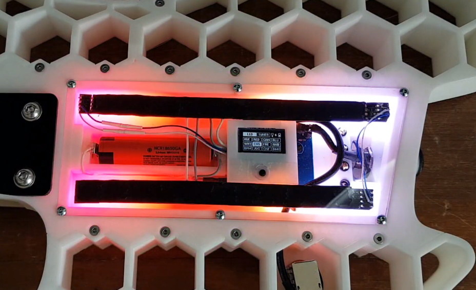
While the skeletal plastic body of the guitar is certainly visually interesting in itself, it only makes up for half of the final look. Inside the central cavity, [Joshendy] has embedded two strips of RGB LEDs, a 128×64 OLED screen, and a custom PCB that plays host to a STM32L4 microcontroller the appropriate voltage regulators necessary to run it all on a battery pack.

The board taps into the audio being produced by the guitar and uses a fast Fourier transform (FFT) to get the LEDs reacting to the beat. As demonstrated in the video after the break, you can use the screen to navigate through the different lighting modes in real-time right on the instrument itself.

We covered the equally impressive large-format 3D printer that [Joshendy] used to produce this guitar earlier in the month, and it’s quite exciting to see the sort of things he’s printing on it already. This project has already set the bar very high, and we can’t wait to see what he comes up with next.

Continue reading “Illuminated 3D Printed Guitar Is Ready To Rock”

Infinity Mirror Guitar Shreds Forever

Just when we thought there was nothing left to make into an infinity mirror, [Burls Art] goes and builds something that seems obvious now that it exists — an infinity mirror guitar. Check out the build video after the break, where [Burls Art] gets right to it without wasting any time.

He started by making a 3/4″ wood frame for the body and the one-piece neck and headstock. The acrylic on the top has two-way mirror film, and the back piece is painted with mirror paint to get the infinity effect going. [Burls Art] also fashioned acrylic boxes for the pickup and the electronics. Those are both buffed to be frosty, so the lights reflect nicely off of them.

There’s nothing super-fancy going on with the electronics, just some app-controlled RGB LEDs. We would love to see a version where the LEDs respond in real time to the music. The effect is still quite cool, so if you don’t want to watch the whole build, at least check out the demo at the end where [Burls Art] plays a riff. Never has a delay pedal been so appropriate.

If you’re not much of a luthier, don’t fret about not being able to make a cover version. We’ve seen plenty of infinity mirrors, but if you want something useful, whip up some infinity drink coasters.

Continue reading “Infinity Mirror Guitar Shreds Forever”

Bonsai LED Matrix Has Chaotic Roots

Most people don’t hand solder their surface mount LED matrices these days, and they certainly don’t do it with RGB LEDs. [fruchti] isn’t most people, has managed to grow his electronic hobby into the art form know as Bonsai.

The organic shapes of miniature trees grown over the course of decades is the ultimate indicator of patience and persistence. For those who prefer bending copper to their will rather than saplings, producing an LED tree that looks and functions this well is an accomplishment that signals clever planning and patient fabrication. The animated result is a masterpiece that took about eighteen months to complete.

There are 128 enamel-coated wires that twist into branches holding 32 RGB light-emitting diodes. Tapping into each at the base of the tree is a chaotic mess made a bit easier by a cleverly designed circuit board.

A circular petal pattern was laid out in Inkscape that includes a hole at the center for the “trunk” to pass through. The LED matrix is designed with 8 rows and 12 columns, but 24 pads were laid out so that only four wires would need to be soldered to each copper petal. Even so, look at the alligator clip holding up this PCB to get an idea of the scale of this job!

The angular base is itself made of copper clad board soldered on the inside of the seams and painted black on the outside. This hides the “petal” PCB, as well as a breakout board for an STM32 microcontroller and a power management circuit that lets you use your choice of USB or a lithium battery.

We wonder if [fruchti] has thought about adding some interactivity to his sapling. While we haven’t seen such a beautiful, tiny, creation as this, we have seen an LED tree whose lights can be blown out like birthday candles. Wouldn’t this be an excellent entry in our Circuit Sculpture challenge? There’s still a few weeks left!

Lo-Fi Art On A 32×32 Matrix

Display technology has improved by leaps and bounds over the last few years, thanks in no small part to the smartphone revolution. High-resolution LCD panels are dirt cheap and easy to interface with. There’s absolutely no logical reason to try and show images on a 32×32 array of RGB LEDs. But that didn’t stop [Felix Spöttel] from doing it anyway.

The project, which he calls thirtytwopixels, was designed to work in conjunction with MPD (Music Player Daemon) to show the album art for whatever is currently playing. The ultra-low resolution display added a certain element of abstractness to the artwork, which [Felix] said made it an interesting conversation starter. Guests would try and guess what the album art was depicting given the sparse rendition shown on the matrix.

[Felix] gives an excellent explanation of how to get the server and client-side software up and running should you want to recreate his setup, but his Python scripts also have a function where you can push an arbitrary image to the display if you don’t want to connect everything up to the MPD backend.

On the hardware side, thirtytwopixels uses the Raspberry Pi Zero W, a Adafruit RGB Matrix Bonnet, and a 32×32 LED matrix that uses the HUB75 interface. Even a relatively small LED matrix like this can get pretty thirsty, so [Felix] is using a 5 volt power supply that can deliver 4 amps to keep the electronics happy.

If you wanted to keep the low resolution aesthetic but make the display larger, we’ve seen WS2812B LED strips and 3D printed frames used to make a custom jumbo matrix which could surely be adapted for this concept.

Porting QMK To A Cheap Mechanical Keyboard

Over the last couple of years, we’ve seen an incredible number of DIY keyboard builds come our way. Some have had their switches nestled into laser-cut aluminum and others 3D printed plastic. They may be soldered together on a custom PCB, or meticulously hand-wired. But however they were built, they almost all shared one thing in common: they ran some variant of the open source QMK keyboard firmware.

But what if you just want to run an open firmware on the keyboard you picked up for $50 bucks on Amazon? That’s exactly where [Stephen Peery] found himself nine months ago with this DK63 gaming keyboard. Since so many of these small RGB LED mechanical keyboards are very similar to existing open source designs, he wondered what it would take to blow out the original firmware and replace it with a build of QMK.

While [Stephen] doesn’t have everything working 100% yet, he’s nearly reached the end of his epic reverse engineering journey. The first step was tearing apart the keyboard and identifying all the components it used, then pulling the original firmware out of the updater. From there, between Ghidra and Serial Wire Debug, he was able to figure out most of what the stock firmware was doing so he could replicate it in QMK.

According to his README, the RGB LEDs and Bluetooth functionality don’t currently work, but other than that it seems QMK is up and running. If you’re OK with those concessions, he has information on the page about flashing his build of QMK to the stock DK63 with the ST-Link V2 so you can give it a shot. Though you do so at your own risk; we wouldn’t recommend doing this on your only keyboard.

We’ve seen commercially manufactured keyboards running QMK before, but it usually involves completely replacing the original controller with new electronics. That [Stephen] got this all working on stock hardware so other owners can follow in his footsteps is really a considerable accomplishment.

[Thanks to Baldpower for the tip.]

The Amazing Technicolor Parts Organizer

It wouldn’t be much of an exaggeration to say that anyone reading these words has struggled at one time or another to keep an ever growing collection of electronic bits and bobs from descending into absolute chaos. Tossing them all into plastic bins is at least a start down the road to long-term organization, but they still needed to be sorted and inventoried if you want to avoid the wasted time and money of buying parts you forgot you already had.

For his latest project, [Zack Freedman] decided to finally tackle the personal parts collection that he’s ended up lugging around for the last several years. The first half of the battle was just figuring out what he actually had, what he was likely to need down the line, and getting it all sorted out so he didn’t have to keep rummaging through a big pile to find what he needed. But it’s not enough to get organized, you also need to stay organized.

Which is why he then turned his attention to how all these newly sorted components would actually be stored going forward. He already had a trio of Harbor Freight bin organizers, but as one expects from that fine retailer, they were only marginally suitable for the task at hand. So [Zack] designed a 3D printed faceplate that could snap onto the original plastic bin. The new fronts made them easier to grab and featured an opening to accept a laser-etched plastic label.

To give them a little visual flair, he decided to print the faceplates using rainbow gradient filament. To prevent them from being random colors, he used the relatively obscure sequential slicing option so his Prusa i3 would print each faceplate in its entirety before moving over to the next one on the bed. This took far longer than doing them in parallel (especially since he had access to multiple printers), but makes for a much nicer aesthetic as the color smoothly transitions between each bin on the wall. It also has a practical benefit, as you can tell at a glance if any of the bins have found themselves in the wrong spot.

If you really want to go off the deep end, we’ve seen hackers light individual bins with RGB LEDs tied into a searchable inventory system. But for most hobbyists, simply learning when to purge would be more practical.

Continue reading “The Amazing Technicolor Parts Organizer”

Raspberry Pi Helps Racer Master The Track

Looking to give himself a competitive edge, racer [Douglas Hedges] wanted to come up with a system that could give him real-time feedback on how his current performance compared to his previous fastest lap time. Armed with a Raspberry Pi and some Python libraries, he set out to add a simple telemetry system to his car. But as is often the case with these kind of projects, things just started snowballing from there.

The Raspberry Pi based data acquisition system.

At the most basic level, his system uses GPS position and speed information to light up a strip of RGB LEDs on the dashboard: green means he’s going faster than the previous best lap, and red means he isn’t. Any interface more complex than that would just be a distraction while he focuses on the track. But that doesn’t mean the Raspberry Pi can’t collect data for future review after the race is over.

With the basic functionality in place, [Douglas] turned his attention to collecting engine performance data. It turned out the car already had some pre-existing equipment for collecting metrics such as the air-fuel ratio and RPM, which he was able to connect to the Raspberry Pi thanks to its use of a well documented protocol. On top of that he added a Labjack U3 data acquisition system which let him pull in additional information like throttle position and coolant temperature. Grafana is used to visualize all of this data after the race, though it sounds like he’s also considering adding a cellular data connection vehicle data can be streamed out in real-time.

In the past we’ve seen onboard data collection systems make real-world races look more like their virtual counterparts, but it seems like the solution [Douglas] has come up with is more practical in the heat of the moment.

Continue reading “Raspberry Pi Helps Racer Master The Track”