Pen Plotter Uses Polar Coordinates

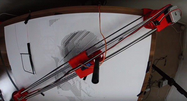
To keep track of a location in a two-dimensional space, two measurements are needed. Most of the time, we would naturally think to do this by the Cartesian method, measuring position along one axis and then again along a second axis. But this isn’t the only way of keeping track of position. Polar coordinates, where the distance from the origin and an angle are used as the two measurements, works just as well, and sometimes can be a preferred method. This pen plotter tosses the expected Cartesian methodology we would typically expect in favor of this polar system.

The first prototype that [André] built was a good proof of concept. A pen attached to a movable carriage on a single rotating arm produced passable drawings, but as all prototypes go this one needed some refinement. Limit switches at the ends of the table, as well as within the arm, served to orient the plotter so that it didn’t manually need to be zeroed out every time. A linear actuator was added to give finer control over the pen’s pressure on the table, and finally an encoder was added to the base of the plotter to more accurately correct positional errors in the rotating arm mechanism.

With everything said and done, the polar coordinate plotter seems to work just as well as its Cartesian cousins might, orienting it like this has some advantages as well. Specifically, it is more adapted to drawing curves or circles than an X-Y device might be able to, like we saw with this similar sand-drawing plotter. Also, if allowed to rotate its entire 360-degree reach instead of just the 90 degrees shown in the video, a machine like this could theoretically reach a wider workspace more easily than other plotters.

Continue reading “Pen Plotter Uses Polar Coordinates”

Hackaday Prize 2023: Circuit Scout Lends A Hand (Or Two) For Troubleshooting

Troubleshooting a circuit is easy, right? All you need is a couple of hands to hold the probes, another hand to twiddle the knobs, a pair of eyes to look at the schematic, another pair to look at the circuit board, and, for fancy work, X-ray vision to see through the board so you know what pads to probe. It’s child’s play!

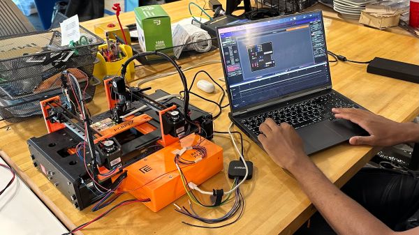
In the real world, most of us don’t have all the extra parts needed to do the job right, which is where something like CircuitScout would come in mighty handy. [Fangzheng Liu] and [Thomas Juldo]’s design is a little like a small pick-and-place machine, except that instead of placing components, the dual gantries place probes on whatever test points you need to look at. The stepper-controlled gantries move independently over a fixture to hold the PCB in a known position so that the servo-controlled Z-axes can drive the probes down to the right place on the board.

As cool as the hardware is, the real treat is the software. A web-based GUI parses the PCB’s KiCAD files, allowing you to pick a test point on the schematic and have the machine move a probe to the right spot on the board. The video below shows CircuitScout moving probes from a Saleae logic analyzer around, which lets you both control the test setup and see the results without ever looking away from the screen.

CircuitScout seems like a brilliant idea that has a lot of potential both for ad hoc troubleshooting and for more formal production testing. It’s just exactly what we’re looking for in an entry for the Gearing Up round of the 2023 Hackaday Prize.

Continue reading “Hackaday Prize 2023: Circuit Scout Lends A Hand (Or Two) For Troubleshooting”

GrblHAL CNC Controller Based On RP2040 Pico

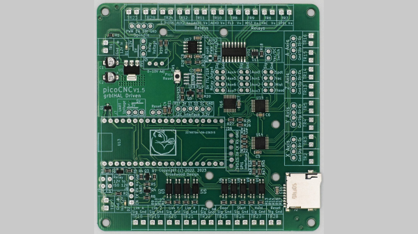
[Phil Barrett] designed a new CNC controller breakout board called the PicoCNC which uses the Raspberry Pi Pico RP2040 module and grblHAL. It packs a bunch of features typical of these controllers, and if you use the Pico W, you get WiFi connectivity along with USB. And if you don’t want connectivity, you can execute G-code directly from a micro SD card. The board is available in kit form, and schematics are posted on the GitHub repository above. Some of the features include four axes of motion, spindle control, limit switches, relay drivers, expansion headers, and opto-isolation.

This isn’t [Phil]’s first controller board. He also designed the grblHAL-based Teensy CNC controller breakout board, a step up from the usual Arduino-based modules at the time and boasting Ethernet support as well. According to the grblHAL site, nine different processors are now supported. There are well over a dozen CNC controller breakout boards listed as well. And don’t forget [bdring]’s 6-Pack grbl-ESP32 controller, a modular breakout board we covered a few years back. So pick your favorite board or roll your own and get moving.

Laser Engraver Uses All Of The DVD Drive

For the last ten to fifteen years, optical drives have been fading out of existence. There’s little reason to have them around anymore unless you are serious about archiving data or unconvinced that streaming platforms will always be around. While there are some niche uses for them still, we’re seeing more and more get repurposed for parts and other projects like this tabletop laser engraver.

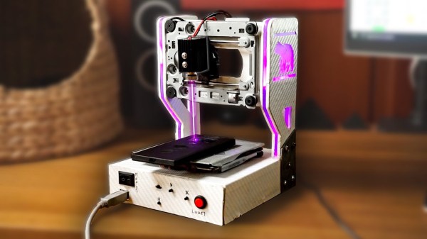
The build starts with a couple optical drives, both of which are dismantled. One of the shells is saved to use as a base for the engraver, and two support structures are made out of particle board and acrylic to hold the laser and the Y axis mechanism. Both axes are made from the carriages of the disassembled hard drives, with the X axis set into the base to move the work piece. A high-output laser module is fitted to the Y axis with a heat sink, and an Arduino and a pair of A4988 motor controllers are added to the mix to turn incoming G-code into two-dimensional movement.

We’ve actually seen a commercial laser engraver built around the same concept, but the DIY approach is certainly appealing if you’ve got some optical drives collecting dust. Otherwise you could use them to build a scanning laser microscope.

Continue reading “Laser Engraver Uses All Of The DVD Drive”

Adding Two Axes Makes CNC Router More Than The Sum Of Its Parts

The problem with building automated systems is that it’s hard to look at any problem and not see it in terms of possible automation solutions. Come to think of it, that’s probably less of a bug and more of a feature, but it’s easy to go overboard and automate all the things, which quickly becomes counterproductive in terms of time and money.

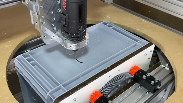
If you’re clever, though, a tactical automation solution can increase your process efficiency without breaking the budget. That’s where [Christopher Helmke] seems to have landed with this two-axis add-on fixture for his CNC router. The rig is designed to solve the problem of the manual modification needed to turn off-the-shelf plastic crates into enclosures for his line of modular automation components, aspects of which we’ve featured before. The crates need holes drilled in them and cutouts created in their sides for displays and controls. It’s a job [Christopher] tackled before with a drill and a jigsaw, with predictable results.

To automate the job without going overboard, [Christopher] came up with a tilting turntable that fits under the bed of the CNC router and sticks through a hole in the spoil board. The turntable is a large, 3D printed herringbone gear driven by a stepper and pinion gear. A cheap bearing keeps costs down, while a quartet of planetary gears constrain the otherwise wobbly platform. The turntable also swivels 90 degrees on a herringbone sector gear; together, the setup adds pitch and roll axes to the machine that allow the spindle access to all five sides of the crates.

Was it worth the effort? Judging by the results in the video below, we’d say so, especially given the number of workpieces that [Christopher] has to process. Add in the budget-conscious construction that doesn’t sacrifice precision too much, and this one seems like a real automation win.

Continue reading “Adding Two Axes Makes CNC Router More Than The Sum Of Its Parts”

DIY Laser For Ablating Metal

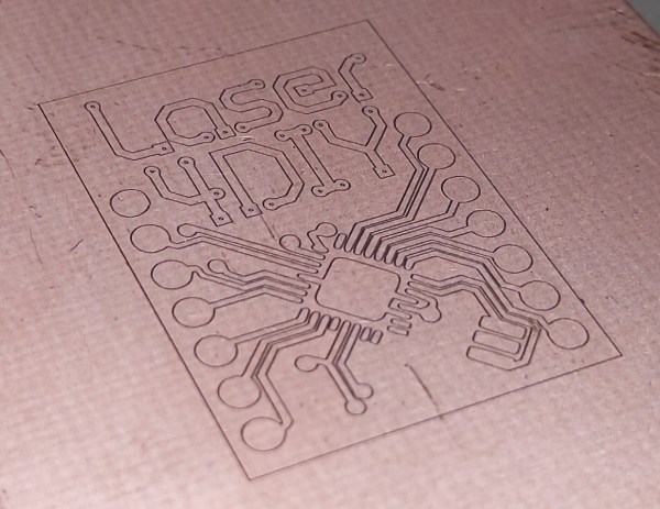
For those who wish to go beyond through-hole construction on perfboard for their circuit boards, a printed circuit board is usually the next step up. Allowing for things like surface-mount components, multi-layer boards, and a wider array of parts, they are much more versatile but do have a slight downside in that they are a little bit harder to make. There are lots of methods for producing them at home or makerspace, though, and although we’ve seen plenty of methods for their production like toner transfer, photoresist, and CNC milling, it’s also possible to make them using laser ablation, although you do need a special laser to get this job done.

The problem with cutting copper is that it reflects infra-red, so a higher-wavelength blue green laser is used instead. And because you want to ablate the copper, but not melt the surrounding areas or cut straight through the board, extremely short, high-power pulses are the way to go. Here, the [Munich Fab Lab] is using 9 kW pulses of around 30 microseconds each.  With these specifications the copper is ablated from the surface of the board allowing for fine details in the range of about 20 µm, which is fine enough for just about any circuit board. The design of the laser head itself is worth a look.

Aside from the laser, the rest is standard CNC machine fodder, but with an emphasis on safety that’s appropriate for a tool in a shared workspace, and the whole project is published under an open license and offers an affordable solution for larger-scale PCB production with extremely fine resolution and without the need for any amounts of chemicals for the more common PCB production methods. There is a lot more information available on the project’s webpage and its GitHub page as well.

Of course, there are other methods of producing PCBs by laser if you happen to have a 20 W fiber laser just kicking around.

Spindle Upgrade Makes PocketNC Faster And Smoother

Conventional wisdom says that rigidity is the name of the game when it comes to machine tool performance. After all, there’s got to be a reason for CNC machines that need specialized rigging companies just to deliver them. But is there perhaps a way for the hobby machinist to cheat a little on that?

From the look of [Ryan]’s PocketNC spindle upgrade, it seems like the answer just might be yes. The PocketNC, a much-coveted five-axis CNC mill sized for the home shop, has a lot going for it, but as with most things, there are trade-offs. Chief among these is a lack of the usual huge, heavy castings used for CNC machines, which results in the tendency for the cutting tool to chatter or even stall out if you push the speeds and feeds too far. After a good intro to some of the important metrics of machining, such as “material removal rate,” the video below delves into how MRR affects chip load which in turn results in chatter.

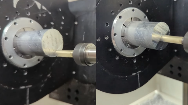
The easy fix for chatter, of course, is to take smaller cuts. But [Ryan] decided to increase the spindle speed to take lighter cuts, but to do it really fast. The hardware for this includes a 3,500 KV high-torque brushless DC motor and a custom spindle attachment. The motor is connected to the spindle shaft using pulleys and a drive belt, and the shaft is supported with stout bearings that can be pre-loaded to fight backlash. The end result is three times the stock 10,000 RPM spindle speed, which lets [Ryan] see a 300% increase in cycle time on his PocketNC. And as a bonus, the whole thing requires no permanent modification to the machine and can be easily removed.

We think [Ryan] did a great job breaking this problem down to the essentials and hacking up a low-cost solution to the problem. Continue reading “Spindle Upgrade Makes PocketNC Faster And Smoother”