Repairing An HDMI Adapter Doesn’t Go So Well

[Adrian] has a lot of retrocomputers, so he uses an RGB to HDMI converter to drive modern monitors. In particular, he has a box that uses a programmable logic chip to read various RGB signals and ships them to a Raspberry Pi Zero to drive the HDMI output. Sounds great until, of course, something goes wrong.

A converter that had worked stopped working due to a bad board with the programmable logic chip on it. Unlike the retrocomputers, this board has little tiny surface mount components. A little analysis suggested that some of the chip pins were not accepting inputs.

Continue reading “Repairing An HDMI Adapter Doesn’t Go So Well”

Barely HDMI Display Gets A Steampunk-Inspired Enclosure

It’s an interesting question: What does one do for a follow-up to building the world’s worst HDMI display? Simple — stick it in a cool steampunk-inspired case and call it a day.

That seems to have been [mitxela]’s solution, and please don’t take our assessment as a knock on either the original build or this follow-up. [mitxela] himself expresses a bit of wonder at the attention garnered by his “rather stupid project,” which used the I2C interface in an HDMI interface to drive a tiny monochrome OLED screen. Low refresh rate, poor resolution — it has everything you don’t want in a display, but was still a cool hack that deserved the attention it got.

The present work, which creates an enclosure for the dodgy display, is far heavier on metalworking than anything else, as the video below reveals. The display itself goes in a small box that’s machined from brass, while the HDMI plug gets a sturdy-looking brass housing that makes the more common molded plastic plug look unforgivably flimsy — hot glue notwithstanding. Connecting the two is a flexible stalk, allowing it to plug into a computer’s HDMI port and giving the user the flexibility to position the nearly useless display where it can be seen best.

But again, we may be too harsh in our judgment; while DOOM is basically unplayable on the tiny display, “Bad Apple!!” is quite watchable, especially when accompanied by [mitxela]’s servo-controlled MIDI music box. And since when has usability been a criterion for judging a hack’s coolness, anyway?

Continue reading “Barely HDMI Display Gets A Steampunk-Inspired Enclosure”

An 128x64 OLED display with a weird image on it, showing a mouse cursor, date and time in the bottom right corner, and a whole lot of presumably dithered dots

Making Your Own Technically-HDMI OLED Monitor

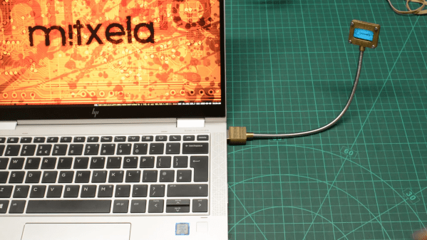
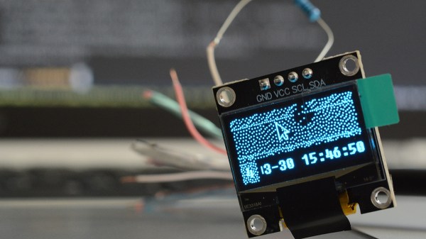
One day, [mitxela] got bored and decided to build his own HDMI monitor – the unconventional way. HDMI has a few high-speed differential pairs, but it also has an I2C interface used for detecting the monitor’s resolution and issuing commands like brightness control. In fact, I2C is the backbone for a lot of side channels like these – it’s also one of our preferred interfaces for connecting to cool sensors, and in this case, an OLED display!

[mitxela] describes his journey from start to end, with all the pitfalls and detours. Going through the pinout with a broken hence sacrificial HDMI cable in hand, he figured out how to probe the I2C lines with Linux command-line tools and used those to verify that the display was recognized on the HDMI-exposed I2C bus. Then, he turned to Python and wrote a short library for the display using the smbus bindings – and, after stumbling upon an FPS limitation caused by SMBus standard restrictions, rewrote his code to directly talk to the I2C device node, raising FPS from 2 to 5-10.

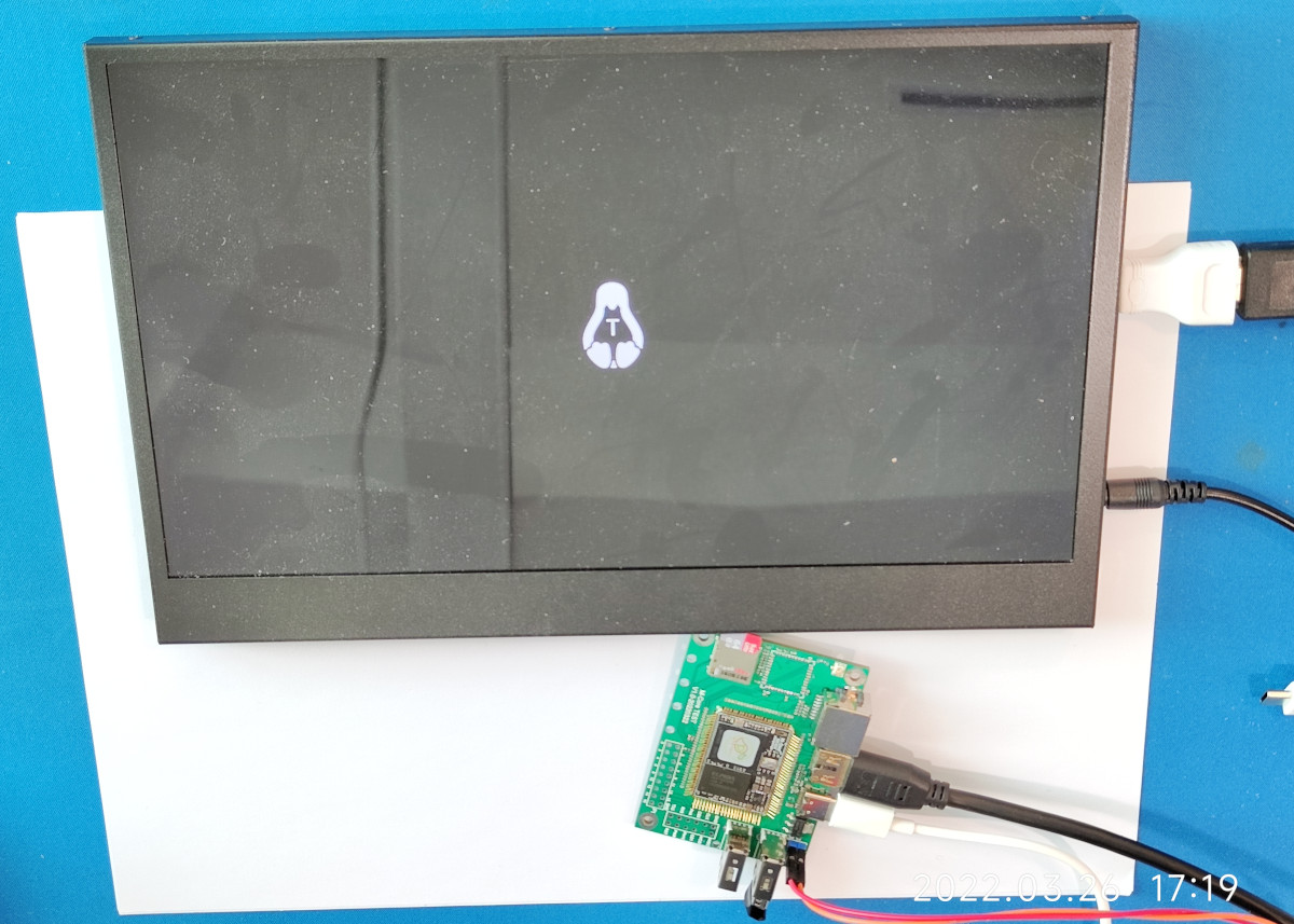
From there, question arose – what’s the best software route to take? He tried making a custom X modeline on the HDMI port the display was technically attached to, but that didn’t work out. In the end, he successfully employed the Linux capability called “virtual monitors”, and found out about an interesting peculiarity – there was no mouse cursor to be seen. Turns out, they’re typically hardware-accelerated and overlaid by our GPUs, but in [mitxela]’s case, the GPU was not involved, so he added cursor support to the picture forwarding code, too.

With partial refresh, the display could be redrawn even faster, but that’s where [mitxela] decided he’s reached a satisfactory conclusion to this journey. The write-up is a great read, and if videos are more your forte, he also made a video about it all – embedded below.

We first covered the ability to get I2C from display ports 14 years ago, and every now and then, this fun under-explored opportunity has been popping up in hackers’ projects. We’ve even seen ready-to-go breakouts for getting I2C out of VGA ports quickly. And if you go a bit further, with your I2C hacking skills, you can even strip HDCP!

We thank [sellicott] and [leo60228] for sharing this with us!

Continue reading “Making Your Own Technically-HDMI OLED Monitor”

An M-Core module plugged into its devboard. Around it are Ethernet, HDMI, Type-C, two USB-A ports, one MicroSD card socket and one unpopulated footprint for a WiFi module

MangoPi To Bring A SD-Card-Sized Linux Module

Today’s Diminutive Device is a small castellated System-On-Module (Twitter link, nitter proxy) from [MangoPi] called M-Core, with a quad-core A53 CPU and 1 GB of RAM. As such, it’s very capable of running Linux, and even sports an HDMI output! Taking a closer look at the devboard picture, we can spot traces for three USB 2.0 ports, what seems to be two SDIO interfaces for MicroSD or WiFi cards, and an Ethernet MagJack with its termination network. This is a decent set of interfaces, rivaling what we’d expect out of a Pi Zero!

More importantly, this module is as small as an SD card itself – or as an OLED display that we hobbyists sprinkle onto our projects. Having power of Linux in such a small footprint is certainly something to behold! The back of the module is mostly flat, save for a few decoupling capacitors on the other side of the CPU – it seems, an Allwinner H616. On top of it, we can see the CPU itself, a small buck regulator and a DDR3 RAM chip, as well as tightly-packed passives. There’s even an unpopulated footprint for a DFN8 QSPI flash chip – with a lightweight enough OS build, you could perhaps dedicate your MicroSD card to storage only.

The devboard for uses the “FlexyPins”-like connectivity technique we’ve covered recently, and [MangoPi] say they bought those pins on TaoBao. We can’t help but be a bit amused at the thought of putting HDMI through such connections, but it seems to work well enough! Castellated modules like these are relatively easy to work with, so it shouldn’t be hard to literally pop this module out of the devboard and figuratively pop it onto your PCB. Next step is, reportedly, porting Armbian to this board, likely solving quite a few software support hurdles.

MangoPi have been posting updates on their Twitter page over the last few weeks, and, as it comes with the format, a lot of questions are left unanswered. Why does the devboard only show a single linear regulator of the kind we typically expect to deliver 1 A at most? Will we get higher-RAM versions? What’s the price going to look like? Will this module ever get to market? We can only hope, but if it does indeed, we are sure to see a few projects with these, whether it’s smart glasses, smart displays, phones, handhelds or malicious wall chargers. As usual, community makes or breaks an SBC, and we shall watch this one closely.

We thank [WifiCable] and [DjBiohazard] for sharing this with us!

The Label Says HDMI 2.1 But That Doesn’t Mean You’ll Get It

Technology moves quickly these days as consumers continue to demand more data and more pixels. We see regular updates to standards for USB and RAM continually coming down the pipeline as the quest for greater performance goes on.

HDMI 2.1 is the latest version of the popular audio-visual interface, and promises a raft of new features and greater performance than preceding versions of the standard. As it turns out, though, buying a new monitor or TV with an HDMI 2.1 logo on the box doesn’t mean you’ll get any of those new features, as discovered by TFT Central.

Continue reading “The Label Says HDMI 2.1 But That Doesn’t Mean You’ll Get It”

A Game Boy connected to a monitor while playing Super Mario Land 2

FPGA Boards Add VGA And HDMI Interfaces To The Original Game Boy

The classic Game Boy remains a firm favorite in the realm of retrocomputing. Revolutionary as it was at the time, by today’s standards its display is rather primitive, with no backlight and a usable area measuring only 47 mm x 44 mm. [Martoni] figured out a way to solve this, by developing GbVGA and GbHdmi, two projects that enable the Game Boy to connect to an external monitor. This way, you can play Super Mario Land without straining your eyes, and we can also image potential uses for those who stream their gameplay online.

A Game Boy connected to a monitor while playing Super Mario Land 2 
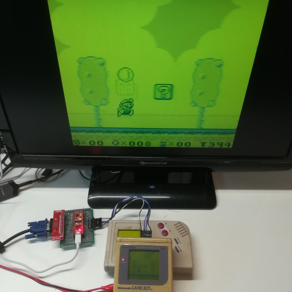
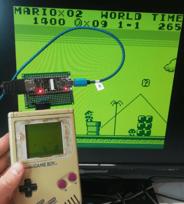
Getting the image data out of the Game Boy is surprisingly straightforward, and has been done a few times before. Basically, the connection between the CPU and the LCD screen is a serial interface with a 4 MHz clock, two data lines and two sync lines. [Martoni] uses pin headers sticking out of the Game Boy’s plastic case to connect these to a small FPGA board. The board in question is a Fireant for the VGA version and a Tang Nano 4K for the HMDI model. In either case the FPGA reads out each frame from the Game Boy’s LCD interface and draws the extracted image onto the monitor, using the same four shades of green as used on the original screen.

[Martoni] states that the ultimate goal of these projects is to make a Switch-like docking station for the original Game Boy, which is definitely something we’re looking forward to. Although adding external monitors to the Game Boy is not entirely new, we like the simplicity of this implementation and the fact that anyone can improve upon it thanks to the full source code being available. Similar hacks have been performed on the newer Game Boy Pocket and Game Boy Advance as well.

magicBlueSmoke-piStick-featured

How Do You Make A Raspberry Pi On A Stick?

We agree with [magic-blue-smoke] that one of the only things more fun than a standard Raspberry Pi 4 is the Compute Module form factor. If they are not destined to be embedded in a system, these need a breakout board to be useful. Each can be customized with a myriad board shapes and ports, and that’s where the real fun starts. We’ve already seen projects that include custom carrier boards in everything from a 3D Printer to a NAS and one that shows we can build a single-sided board at home complete with high-speed ports.

[magic blue smoke] used this ability to customize the breakout board as an opportunity to create a hackable media player “stick” with the Raspberry Pi built-in. We love that this Raspberry Pi CM4 TV Stick eliminates all the adapters and cables usually required to connect a Pi’s fiddly micro HDMI ports to a display and has heat sinks and an IR receiver to boot. Like a consumer media player HDMI stick, all you need to add is power. Continue reading “How Do You Make A Raspberry Pi On A Stick?”