Hackaday Links Column Banner

Hackaday Links: January 2, 2022

That sound you may have heard in the wee hours of Christmas morning had nothing to do with Santa; rather, it was the sound of a million astronomers collectively letting out their breath around the world as the James Webb Space Telescope survived its fiery ride to space. And not only did it survive, but the ESA launch team did such a good job putting the Ariane rocket on course that NASA predicts the observatory now has enough fuel to more than double its planned ten-year mission. Everything about the deployment process seems to be going well, too, with all the operations — including the critical unfurling of the massive and delicate sunshield — coming off without a hitch. Next up: tensioning of the multiple layers of the sunshield. If you want to play along at home, NASA has a nice site set up to track where JWST is and what its current status is, including temperatures at various points on the telescope.

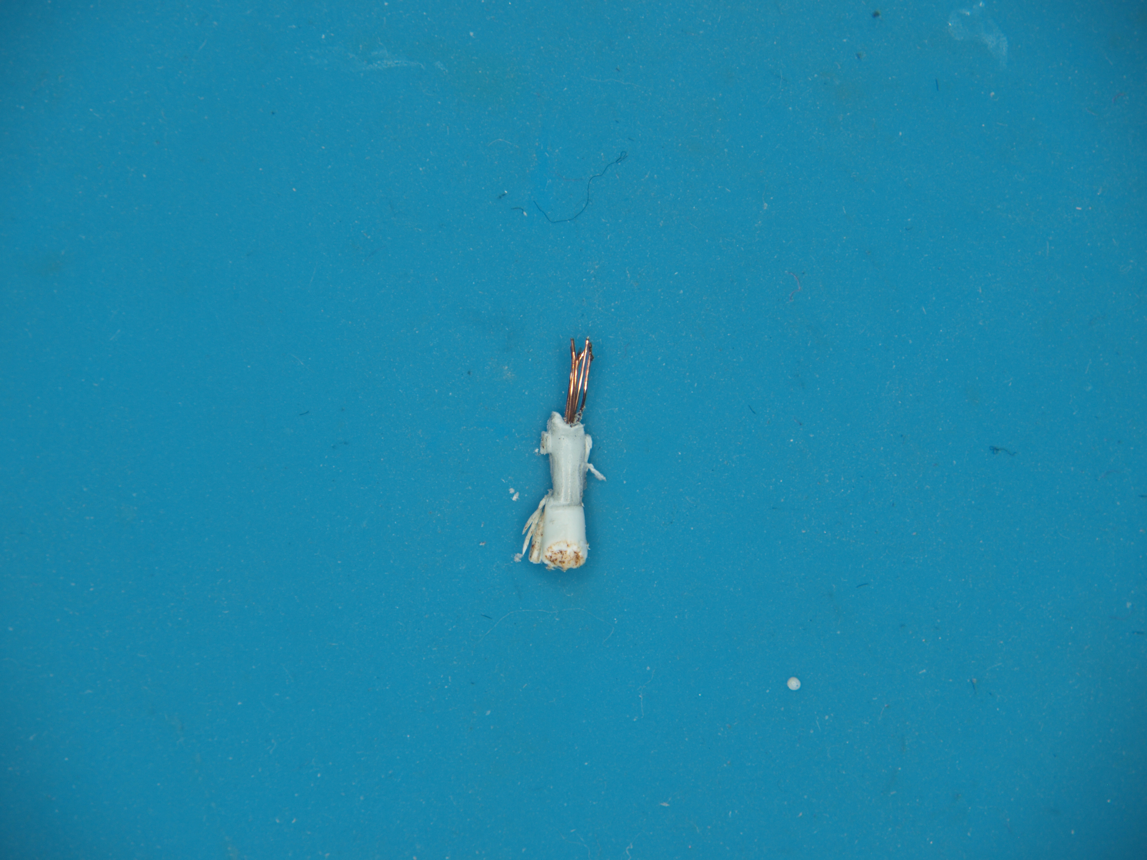
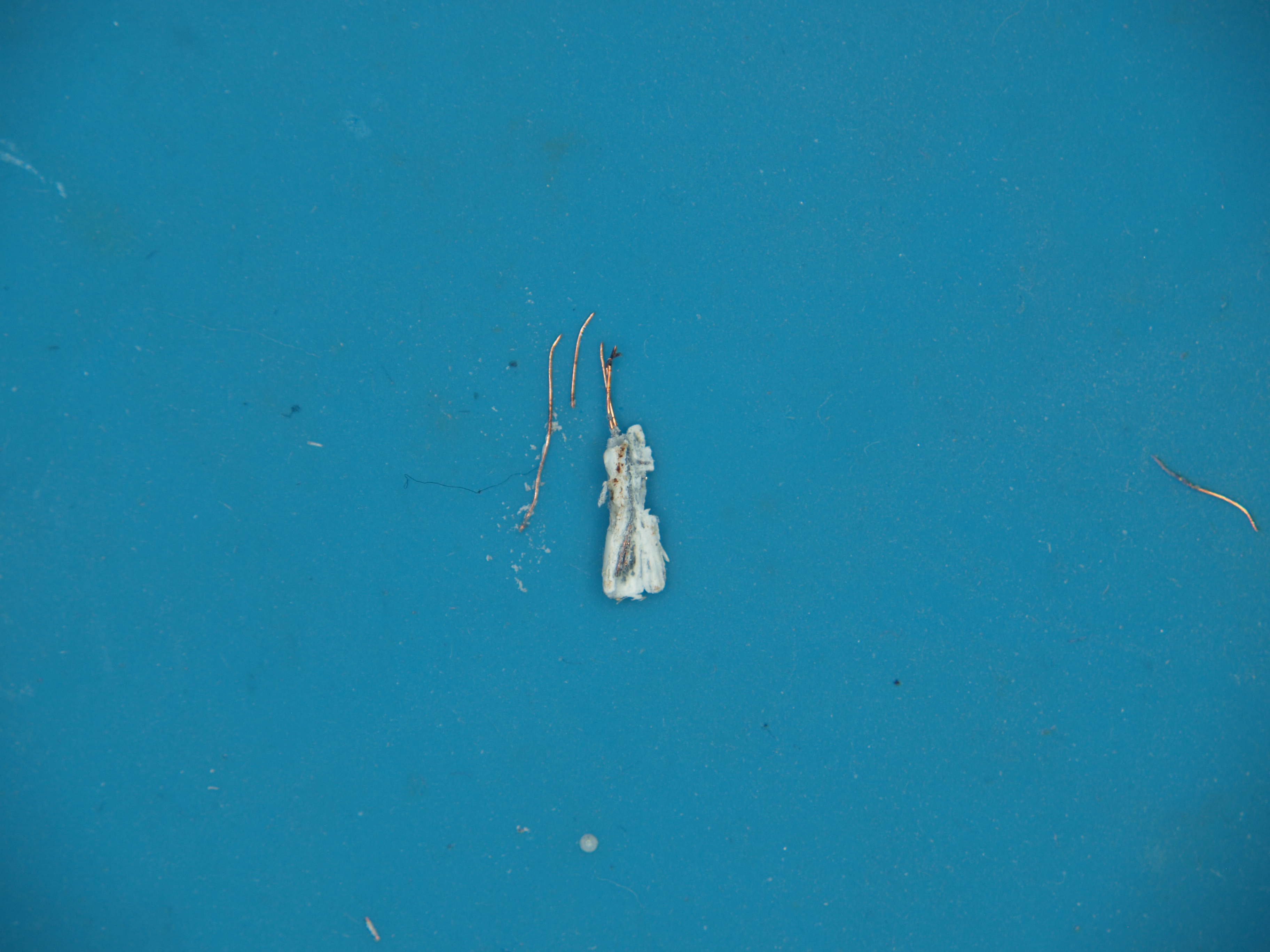
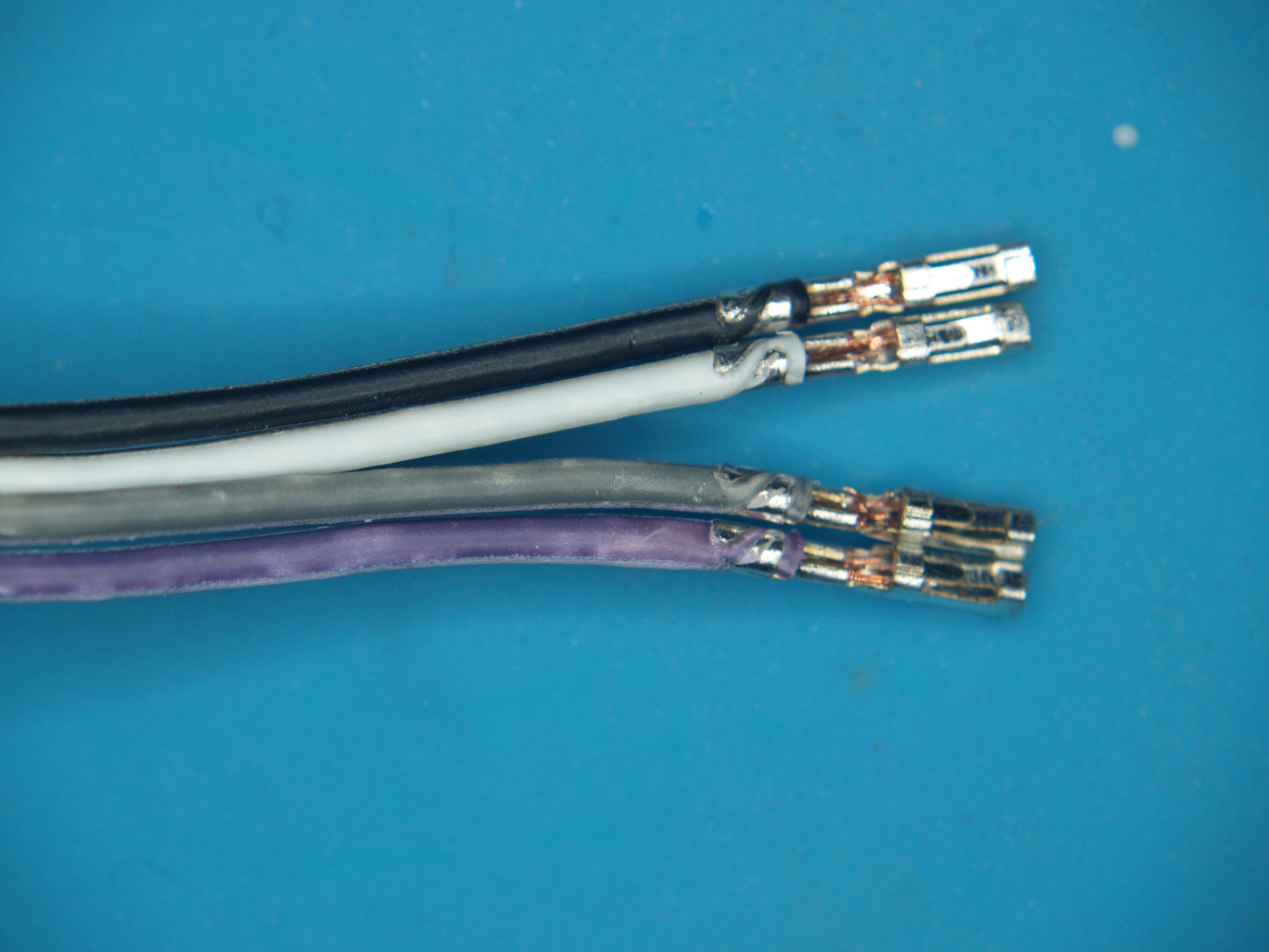
We got a tip from Mark about some dodgy jumper wires that we thought we should share. Low-quality jumpers aren’t really a new problem, but they can really put a damper on the fun of prototyping. The ones that Mark found could be downright dangerous. He got them with a recent dev board purchase; outwardly, they appear fine, at least at first. Upon closer inspection, though, the conductors have turned to powder inside the insulation. Even the insulation is awful, since it discolors when even slightly flexed. He suspects conductors are actually copper-plated aluminum; check out his pictures below and maybe look through your collection for similarly afflicted jumpers.

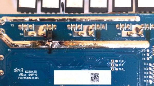
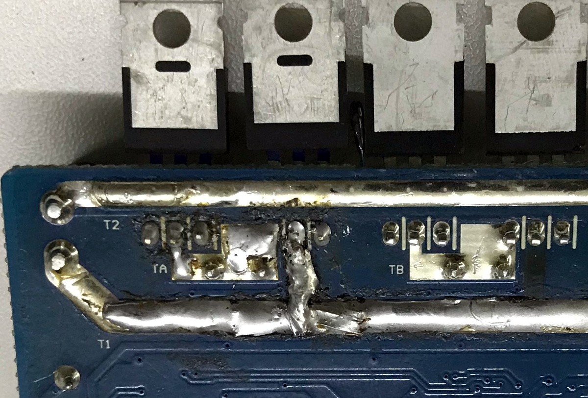
Speaking of dodgy hardware, if you love the smell of melting MOSFETs in the morning, then have we got a deal for you. It seems that a non-zero number of Asus Z690 Hero PC motherboards have suffered a fiery demise lately, stirring complaints and discontent. This led some curious types to look for the root cause, which led to the theory that an electrolytic cap had been installed with the wrong polarity on the dead boards. Asus confirmed the diagnosis, and is doing the right thing as they are “working with the relevant government agencies on a replacement program.” So if you’ve got one of these motherboards, you might want to watch the video below and see how the caps were installed.

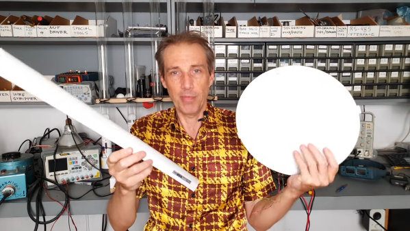
If you’re in the mood for some engineering eye-candy, check out the latest video from Asianometry. They’ve got a finger on the pulse of the semiconductor industry, with particular attention paid to the engineering involved in making the chips we all have come to depend on. The video below goes into detail on the extreme ultraviolet (EUV) light source that fabrication machine maker ASML is developing for the next generation of chip making. The goal is to produce light with a mind-bending wavelength of only 13.5 nanometers. We won’t spoil the details, but suffice it to say that hitting microscopic droplets of tin with not one but two lasers is a bit of a challenge.

And finally, bad luck for 38 people in Tokyo who were part of a data breach by the city’s Metropolitan Police Department. Or rather, good luck since the data breach was caused by the loss of two floppy disks containing their information. The police say that there haven’t been any reports of misuse of the data yet, which is really not surprising since PCs with floppy drives are a little thin on the ground these days. You’d think that this would mean the floppies were left over from the 90s or early 2000s, but no — the police say they received the disks in December of 2019 and February of 2021. We’d love to know why they’re still using floppies for something like this, although it probably boils down to yet another case of “if it ain’t broke, don’t fix it.”

Laptop Gets Fixed By Simply Removing Problem Component

We wouldn’t go so far as to say “don’t try this at home”, but the way [Troy] brought an expensive (but out of warranty) laptop back to life is interesting, even if it shouldn’t be anyone’s Plan A for repair work.

It started with a friend’s Alienware laptop that would only boot to a black screen and get very hot in the process. With the help of a thermal imaging camera and some schematics, [Troy] was able to see that one of the closely-spaced MOSFETs in the power supply appeared to be the culprit. Swapping the power MOSFETs out with replacements seemed a reasonable approach, so armed with a hot air rework station he got to work. But that’s where problems began.

The desoldering process was far from clean, in part because the laptop’s multi-layer PCB had excellent thermal management, sucking away heat nearly as fast as [Troy]’s hot air gun could lay it down. It ended up being a messy slog of a job that damaged some of the pads. As a result, the prospects of soldering on a replacement was not looking good. But reviewing the schematic and pondering the situation gave [Troy] an idea.

An open laptop showing a diagnostic tool on the screen
One expensive laptop, brought back to service.

According to the schematic, the two MOSFETs (at least one of which was faulty) had parallel counterparts on the other side of the board. This is typically done to increase capacity and spread the thermal load somewhat. However, according to the current calculations on the schematic, these parts are expected to handle about 20 A in total, but the datasheets show that each of the MOSFETs could handle that kind of current easily (as long as heat sinking could keep up.) In theory, the laptop didn’t need the extra capacity.

Could the laptop “just work” now that the faulty part had simply been removed? [Troy] and his friend [Mike] were willing to give it a shot, so after cleaning up the mess as best they could, they powered the laptop on, and to their mild surprise, everything worked! Some stress testing with intensive gaming showed that the thermal problems were a thing of the past.

Simply removing a part may not be the best overall repair strategy, but much like shrinking a hot air rework station by simply cutting it in half, it’s hard to argue with results.

DIY Machine Enables PEMF Therapy On A Budget

We’re certainly not qualified to say whether or not pulsed electromagnetic field (PEMF) therapy will actually reduce your stress or improve your circulation, but there seems to be enough legitimate research going on out there that it might be worth a shot. After all, unless you’ve got a pacemaker or other medical implant, it seems pretty unlikely a magnetic field is going to make anything worse. Unfortunately commercial PEMF machines can cost thousands of dollars, making it a fairly expensive gamble.

But what if you could build one for as little as $10 USD? That’s the idea behind the simple DIY PEMF machine [mircemk] has been working on, and judging by its ability to launch bits of metal in the video below, we’re pretty confident it’s indeed producing a fairly powerful electromagnetic field. Even if it doesn’t cure what ails you, it should make an interesting conversation piece around the hackerspace.

While the outside of the machine might look a bit imposing, the internals really are exceptionally straightforward. There’s an old laptop power supply providing 19 VDC, a dual-MOSFET board, a potentiometer, and a simple signal generator. The pulses from the signal generator trip the MOSFET, which in turn dumps the output of the laptop power supply into a user-wound coil. [mircemk] has a 17 cm (6.7 inch) open air version wrapped with 200 turns of copper wire used for treating wide areas, and an 8 cm (3 inch) diameter version with 300 windings for when you need more targeted energy.

Some skepticism is always in order with these sort of medicinal claims, but commercial PEMF machines do get prescribed to users to help promote bone growth and healing, so the concept itself is perhaps not as outlandish as it might seem.

Continue reading “DIY Machine Enables PEMF Therapy On A Budget”

Thousands Of Discrete MOSFETs Make Up This Compact CPU-Less Computer

How long has it been since a computer could boast about the fact that it contained 2,500 transistors? Probably close to half a century now, at a guess. So in a world with a couple of billion transistors per chip, is a 2,500-transistor computer really something to brag about? Yes. Yes, it is.

The CPU-less computer, called the TraNOR by its creator [Dennis Kuschel], is an elaboration on his previous MyNOR, another CPU-less machine that used a single NOR-gate made of discrete transistors as the core of its arithmetic-logic unit (ALU). Despite its architectural simplicity, MyNOR was capable of some pretty respectable performance, and even managed to play a decent game of Tetris. TraNOR, on the other hand, is much more complicated, mainly due to the fact that instead of relying on 74HC-series chips, [Dennis] built every single gate on the machine from discrete MOSFETs. The only chips on the four stacked PCBs are a trio of memory chips; we don’t fault him at all for the decision not to build the memory — he may be dedicated, but even art has its limits. And TraNOR is indeed a work of art — the video below shows the beautiful board layouts, with seemingly endless arrays of SMD transistors all neatly arranged and carefully soldered. And extra points for using Wintergatan’s marble machine melody as the soundtrack, too.

As much as we loved the original, TraNOR is really something special. Not only is it beautiful, but it’s functional — it’s even backward-compatible with MyNOR’s custom software. Hats off to [Dennis] for pulling off another wonderful build, and for sharing it with us.

Continue reading “Thousands Of Discrete MOSFETs Make Up This Compact CPU-Less Computer”

Putting The Magic Smoke Back In A Cooked Scooter

When [Vitor Melon] found out there was a custom firmware (CFW) available for his Xiaomi Mijia M365 Pro electric scooter that would increase his top end speed, naturally he installed it. Who wouldn’t want a little more performance out their hardware? But while the new firmware got the scooter running even better than stock, he does have a cautionary tale for anyone who might decide to ride their Mijia a bit harder than the fine folks at Xiaomi may have intended.

Now to be clear, [Vitor] does not blame the CFW for the fact that he cooked the control board of his Mijia. At least, not technically. There was nothing necessarily wrong with the new code or the capabilities it unlocked, but when combined with his particular riding style, it simply pushed the system over the edge. The failure seems to have been triggered by his penchant for using the strongest possible regenerative breaking settings on the scooter combined with a considerably higher than expected velocity attained during a downhill run. Turns out that big 40 flashing on the display wasn’t his speed, but an error code indicating an overheat condition. Oops.

Results of the PCB repair.

After a long and embarrassing walk home with his scooter, complete with a passerby laughing at him, [Vitor] opened the case and quickly identified the problem. Not only had the some of the MOSFETs failed, but a trace on the PCB had been badly burned through. Judging by the discoloration elsewhere on the board, it looks like a few of its friends were about to join in the self-immolation protest as well.

After a brief consultation with his graybeard father, [Vitor] replaced the dead transistors with higher rated versions and then turned his attention to the damaged traces. A bit of wire and a generous helping of solder got the main rail back in one piece, and he touched up the areas where the PCB had blackened for good measure.

A quick test confirmed the relatively simple repairs got the scooter up and running, but how was he going to prevent it from happening again? Reinstalling the original firmware with its more conservative governor was clearly no longer an option after he’d tasted such dizzying speeds, so instead he needed to find out some way to keep the controller cooler. The answer ended up being to attach the MOSFETs to the controller’s aluminum enclosure using thermal pads. This allows them to dissipate far more heat, and should keep a similar failure from happening again. You might be wondering why the MOSFETs weren’t already mounted this way, but unfortunately only Xiaomi can explain that one.

With their rapidly rising popularity hackers have been coming up with more and more elaborate modifications for electric scooters, and thanks to their wide availability on the second hand market, it’s likely the best is still yet to come when it comes to these affordable vehicles.

Hacking A Non-Dimmable LED Fixture

For most of us, the solution to having a non-dimmable LED light bulb but needing a dimmable one is a simple as a drive to the store to get the right kind of bulb. But that seems downright boring, not to mention wasteful, so when [Leo Fernekes] was faced with this problem, he looked for a way to make a non-dimmable bulb dimmable.

To be fair, there was a financial aspect to this hack, too. [Leo] had a bunch of cheap non-dimmable light fixtures he wanted to put to use. He started with a teardown and reverse-engineering of a light strip, which contains little more than LEDs and a small buck converter. His analysis of the circuit led him to a solution for dimming the light: inserting a MOSFET as a shunt around the LEDs. That and the addition of a diode to isolate the LEDs from the current regulator would allow for simple PWM-control of the lights via a microcontroller.

As is typical with these things, there were complications. [Leo] found that a timing problem resulted in flickering LEDs; the fix came from adding a sync circuit that cleverly leveraged a flip-flop inside the PIC16 microcontroller he chose for the circuit. His prototype incorporates these modifications, plus an interface that supports the DALI protocol for architectural lighting control. As always, [Leo] is quick to point out that mixing line voltage into your projects is not without risks, which he takes pains to mitigate. And as is also typical for his projects, [Leo] gives just the right amount of detail to understand the theory behind his design.

Continue reading “Hacking A Non-Dimmable LED Fixture”

Electric Candle Replaces Flame With Plasma

Ah, the charm of candlelight! Nothing says “romance” — or “extended power outage” — like the warm, soft glow of a real candle. But if you’re not a fan of burning wax for whatever reason, this electric plasma candle may be just the thing to build for your next dinner for two.

This re-imagining of the humble candle comes to us by way of plasma super-fan [Jay Bowles], who has a lot of experience with plasmas and the high-voltage circuits that often go along with them. Even so, he had to enlist help with the circuit, with is essentially a 10-MHz Class-E oscillator, from [Leon] at the Teslaundmehr channel on YouTube. The most prominent feature of the build is the big resonator coil, surrounded by the shorter primary coil and sitting atop the heatsink for the MOSFET driver. [Jay]’s usual acrylic-rich style is well represented here, and the resulting build is quite lovely.

The tuning process, though, sounds like it was pure torture. It took a lot of tweaking — and a lot of MOSFETs — to get the candle to produce a stable flame. But once it did, the results were striking. The plasma coming off the breakout point on the resonator coil is pretty much the same size, shape, and — occasionally — the color as a candle flame. It’s also hot enough to do some damage, so do be careful if you build this. We’ve included both [Jay]’s and [Leon]’s videos below; [Leon]’s has great step-by-step build instructions.

We’ve been following [Jay]’s journey through the plasmaverse for a while now, from his cheap and simple Tesla coils to using corona discharge to clean his hands. He even hosted a Hack Chat on the subject last year.

Note: [Jay] reached out to us after publication about mitigating RF noise. He does his experiments inside a steel-reinforced concrete building with grounded metal screens over the windows. An RF-wizard friend has checked across the spectrum and detected no leaks to the outside. Sounds like the business to us.

Continue reading “Electric Candle Replaces Flame With Plasma”