CNC Upgrade To Guitar Pickup Winding Machine

The idea of winding inductive guitar pickups by hand is almost unthinkable. It uses extremely thin wire and is a repetitive, laborious process that nevertheless requires a certain amount of precision. It’s a prime candidate for automation, and while [Davide Gironi] did exactly that, he wasn’t entirely satisfied with his earlier version. He now has a new CNC version that is more full-featured and uses an ATMega8 microcontroller.

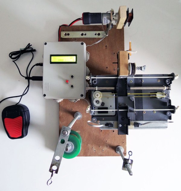
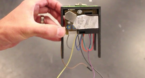
[Davide Gironi]’s previous version took care of winding and counting the number of turns, but it was still an assisted manual system that relied on a human operator. The new upgrade includes a number of features necessary to more fully automate the process, such as a wire tensioner, a wire guide and traverse mechanism (made from parts salvaged from a broken scanner), and an automatic stop for when the correct number of turns has been reached.

guitar_pickup_winding_sample_microscope

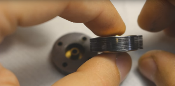
All kinds of small but significant details are covered in the build, such as using plastic and felt for anything that handles the wire — the extremely fine wire is insulated with a very thin coating and care must be taken to not scratch it off. Also, there is the need to compute how far the traverse mechanism must move the wire guide in order to place the new wire next to the previously-laid turn (taking into account the winding speed, which may be changing), and doing this smoothly so that the system does not need to speed up and slow down for every layer of winding.

This system is still programmed by hand using buttons and an LCD, but [Davide Gironi] says that the next version will use the UART in order to allow communication with (and configuration by) computer – opening the door to easy handling of multiple winding patterns. You can see video of the current version in action, below.

Continue reading “CNC Upgrade To Guitar Pickup Winding Machine”

Air Quality Sensors In Every Classroom

One of the first electronics projects for the aspiring hobbyist is wiring a sensor of some sort to a microcontroller, and then doing something useful with the new information. [Brock] has taken this type of gateway project and turned it into a way to get his students involved and familiar with electronics. His take on an air quality meter accomplishes both of these goals, and hopefully helps turn all of his students into the next generation of hackers.

The bill of materials is pretty straightforward. Instead of the go-to Arduino, [Brock] has gone with a Particle Photon which has the added benefits of various wireless connectivity options. The air quality sensor is a Shinyei PP42ns which interfaces easily with the Photon. The only thing that might be out of reach of most public high schools (at least in the United States) is the 3D-printed enclosure, although if you have access to one, [Brock] put the files on the project page so anyone can use them.

Of course, we’re big fans of projects that get students involved in anything beyond standardized tests, and this project goes a long way towards teaching students more than how to pass a test. There are many videos and instructions on the project page if you want to try this on your own, but if the cost for the materials is the only thing scaring you off from doing this in your own classroom there are a few other options. You could use ATtiny chips, or try a different style of sensor, or maybe just try out a different project altogether.

Continue reading “Air Quality Sensors In Every Classroom”

Marvelous MIDI Button Box

Most DJ tools are just ripe for DIY rework. Everything at least speaks MIDI, and the firmware side of the equation that makes a physical interface for your laptop can be downloaded and flashed with minimal effort. And this means that there’s no time better than the present to wire up a ton of buttons to a Teensy and call it a controller.

[UmamiFish]’s build goes the extra mile, though, with a nice laser-cut box and holes for display LEDs as well as the 22 arcade buttons that are packed tightly into the enclosure. A 74HC595 shift-register IC handles the LEDs, but there’s no getting around a bunch of wiring in a build like this. It pays to be neat, and using ribbon cable helps keep some of the chaos under control.

Browsing around Instructables will turn up myriad similar controllers, should the exact configuration of this one not suit your needs. And if you want something with a little more of the real-disk feel, have a look at this controller that uses hard disk platters, or this log of a timecode-vinyl-to-MIDI build.

Hackaday Prize Entry: Visualizing Magnetic Fields

In 1820, Hans Christian Oersted discovered the needle of a compass would deflect when placed next to a wire carrying an electric current. It took 15 years for the first electric motor to be invented following this observation. Humans are dumb, but perhaps they wouldn’t be so oblivious to the basic facts of our reality if they could see magnetic fields. Or if they just had a 3D printer. For his Hackaday Prize entry, [Ted Yapo] is doing just this: adding a magnetic field scanner to a 3D printer, allowing for the visualization of magnetic fields in three dimensions.

The device [Ted] is working on is actually extremely simple, and is mostly implemented in software. The hardware is just a 3D printer with a toolhead consisting of a HMC5883L magnetometer breakout board. This is the simplest and easiest way to find the direction and intensity of a magnetic field, the rest of the work is done in software.

Right now, [Ted] has a setup that will scan a 3D volume with a printer. By placing a magnet in the middle of the print bed, he can visualize the magnetic field inside the volume of his 3D printer. It’s a visualization that is vastly superior to a compass, ferrofluid, or even a mess of iron filings, and is surely a much better pedagogical apparatus for classrooms and science museums alike.

The HackadayPrize2016 is Sponsored by:

How To Make A Custom LCD From Scratch

If you have ever wondered what it took to make your own custom graphic LCD from scratch, this video from [Applied Science] is worth a watch. It’s concise and to the point, while still telling you what you need to know should you be interested in rolling your own. There is also a related video which goes into much more detail about experimenting with LCD technology.

[Applied Science] used microscope slides and parts purchased online to make an LCD that displays a custom graphic when activated. The only step that home experimenters might have trouble following is coating the glass slides with a clear conductive layer, which in the video is done via a process called sputtering to deposit a thin film. You don’t need to do this yourself, though. Pre-coated glass is readily available online. (Search for Indium-Tin Oxide or ‘ITO’ coated glass.)

The LCD consists of a layer of liquid crystal suspended between two layers of conductive glass. An electrical field is used to change the orientation of crystals in the suspension, which modulate the light passing through them. Polarizing filters result in a sharp contrast and therefore a visible image. To show a particular shape, some of the conductive coating is removed from one of the layers in the shape of the desired image. The process [Applied Science] uses to do this is nearly identical to etching a custom PCB. Continue reading “How To Make A Custom LCD From Scratch”

Denver Mini Maker Faire: Fun With Pinball

[Mark Gibson] probably has nothing against silicon. He just knows that a lot that can be done with simple switches, relays, and solenoids and wants to share that knowledge with the world. This was made abundantly clear to me during repeat visits to his expansive booth at Denver Mini Maker Faire last weekend.

In the sunlight-filled atrium of the Museum of Nature and Science, [Mark] sat behind several long tables covered with his creations made from mid-century pinball machines. There are about two dozen pieces in his interactive exhibit, which made its debut at the first-ever Northern Colorado Maker Faire in 2013. [Mark] was motivated to build these boards because he wanted to get people interested in the way things work through interaction and discovery of pinball mechanisms.

fun with pinball thumb
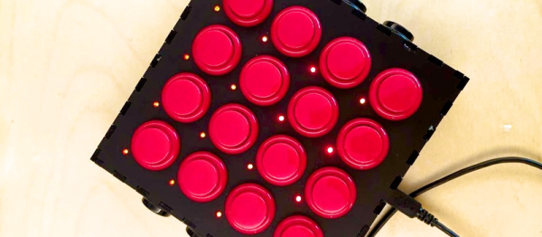
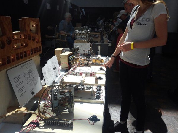
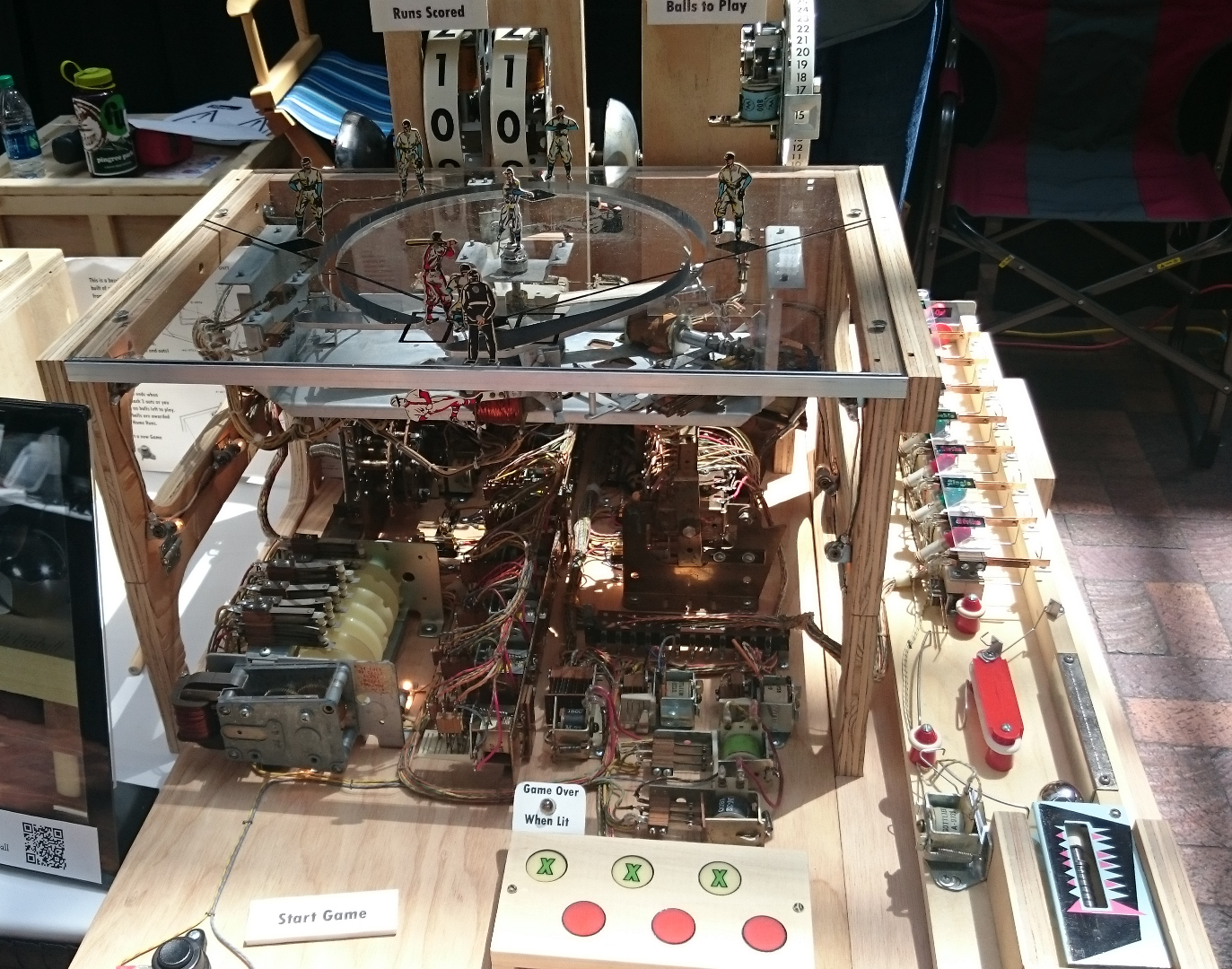
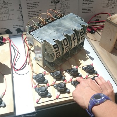
Most of the pieces he has built are single units and simple systems from pinball machines—flippers, chime units, targets, bumpers, and so on—that he affixed to wooden boards so that people can explore them without breaking anything. All of the units are operated using large and inviting push buttons that have been screwed down tight. Each of the systems also has a display card with an engineering drawing of the mechanism and a short explanation of how it works.

[Mark] also brought some of the original games he has created by combining several systems from different machines, like a horse derby and a baseball game. Both of these were built with education in mind; all of the guts including the original fabric-wrapped wires are prominently displayed. The derby game wasn’t working, but I managed to load the bases and get a grand slam in the baseball game. Probably couldn’t do that again in a million summers.

fun with pinball baseball game
Take me out to the Maker Faire! Click to embiggen.

About five years ago, we covered [Mark]’s build of an atomic clock from pinball machine parts. It’s about time we featured his work again. We have shared a lot of pinball-related builds over the years from the immersive to the gigantic to the dankest of the dank.

Micro Tesla Turbine Is An Engineering Tour De Force

A corollary to Godwin’s Law ought to be that any Hackaday post that mentions Nikola Tesla will have a long and colorful comment thread. We hope this one does too, but with any luck it’ll concentrate on the engineering behind this tiny custom-built Telsa turbine.

For those not familiar with Mr. Tesla’s favorite invention, the turbine is a super-efficient design that has no blades, relying instead on smooth, closely spaced discs that get dragged along by the friction of a moving fluid. [johnnyq90]’s micro version of the turbine is a very accomplished feat of machining. Although at first the build appears a bit janky, as it progresses we see some real craftsmanship – if you ever doubt that soda can aluminum can be turned, watch the video below. The precision 25mm rotor goes into a CNC machined aluminum housing; the way the turned cover snaps onto the housing is oddly satisfying. It looks like the only off-the-shelf parts are the rotor bearings; everything else is scratch-made. The second video ends with a test spool-up that sounds pretty good. We can’t wait for part 3 to find out how fast this turbine can turn.

Size matters, and in this case, small is pretty darn impressive. For a larger treatment of a Tesla turbine, see this one made of old hard drive platters.

Continue reading “Micro Tesla Turbine Is An Engineering Tour De Force”