Reviving An Electron Microscope With Arduino

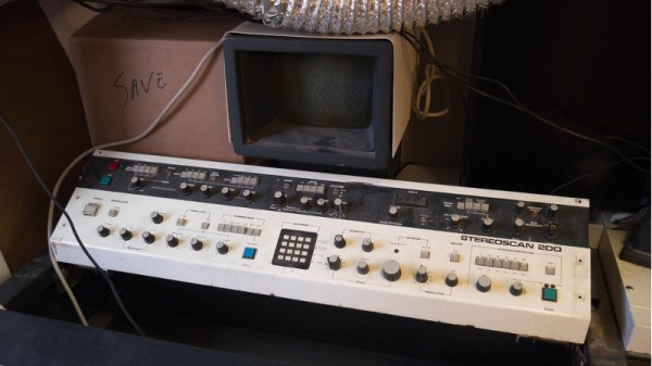
We don’t know about you, but when our friends ask us if we want to help them fix something, they’re usually talking about their computer, phone, or car. So far it’s never been about helping them rebuild an old electron microscope. But that’s exactly the request [Benjamin Blundell] got when a friend from a local hackerspace asked if he could take a look at a vintage Cambridge Stereoscan 200 they had found abandoned in a shed. Clearly we’re hanging out with the wrong group of people.

As you might imagine, the microscope was in desperate need of some love after spending time in considerably less than ideal conditions. While some of the hackerspace members started tackling the hardware side of the machine, [Benjamin] was tasked with finding a way to recover the contents of the scope’s ROM. While he’s still working on verification, the dumps he’s made so far of the various ROMs living inside the Stereoscan 200 have been promising and he believes he’s on the right track.

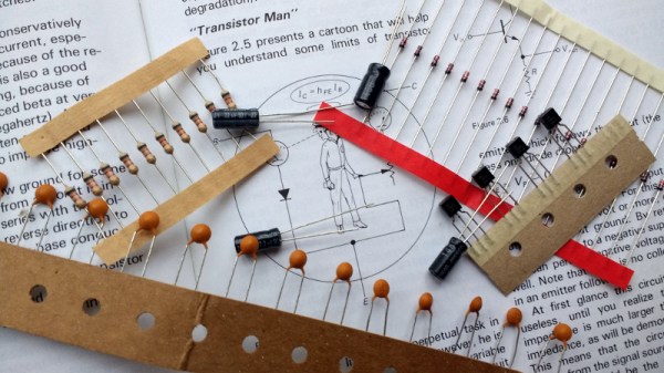
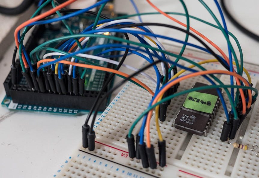
The microscope uses a mix of Texas Instruments 25L32 and 2516 chips, which [Benjamin] had to carefully pry out after making sure to document everything so he knew what went where. A few of the chips weren’t keen on being pulled from their home of 30-odd years, so there were a few broken pins, but on the whole the operation was a success.

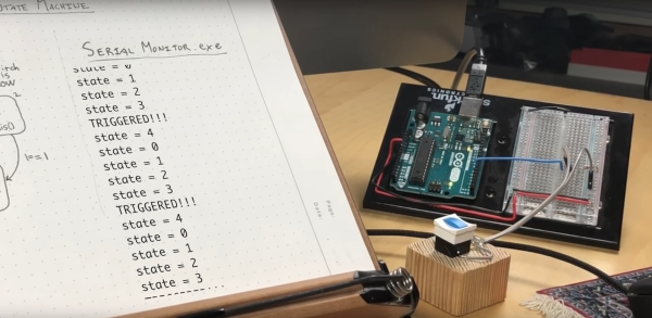
Each chip was placed in a breadboard and wired up to an Arduino Mega, as it has enough digital pins to connect without needing a shift register. With the wiring fairly straightforward, [Benjamin] just needed to write up some code to read the contents of the chip, which he has graciously provided anyone else who might be working on a similar project. At this point he hasn’t found anything identifiable in his ROM dumps to prove that they’ve been made successfully, all he really knows right now is that he has something. At least it’s a start.

More and more of these older electron microscopes are getting a second lease on life thanks to dedicated hackers in their home labs. Makes you wonder if there’s ever going to be a piece of hardware the hacker community won’t bend to their will.

Circuit-Sword Delivers Retro Justice

You can’t search for “retro gaming” without hitting a plethora of single board computers attached to all manner of controls, batteries, etc. Often these projects have an emphasis on functionality above all else but [Kite]’s Circuit-Sword is different. The Circuit-Sword is the heart of a RaspberryPi-based retro gaming machine with an enviable level of fit and finish.

Fundamentally the Circuit-Sword is a single board computer built around a Raspberry Pi Compute Module 3. We don’t see many projects which use a Compute Module instead of the full Pi, but here it is a perfect choice allowing [Kite] to useful peripherals without carrying the baggage of those that don’t make sense for a portable handheld (we’re looking at you, Ethernet). The Circuit-Sword adds USB-C to quickly charge an onboard LiPo (rates up to 1.5A available) and the appropriate headers to connect a specific LCD. The Compute Module omits wireless connectivity so [Kite] added an SDIO WiFi/Bluetooth module. And if you look closely, you may notice an external ATMega mediating a familiar looking set of button and switches.

Optional Drill Holes

We think those buttons and switches are the most interesting thing going on here, because the whole board is designed to fit into an original GameBoy enclosure. It turns out replacement enclosures are available from China in surprising variety (try searching for “gameboy housing”) as are a variety of parts to facilitate the installation of different screen options and more. One layer deeper in the wiki there are instructions for case mods you may want to perform to make everything work optimally. The number of possible options the user can mod-in are wide. Extra X/Y buttons? Shoulder buttons on the back? Play Station Portable-style slide joysticks? All detailed. For even more examples, try searching the SudoMod forums. For example, here’s a very visual build log by user [DarrylUK].

The case mod instructions are worth a glance even if you have no intent to build a device. There are some clever techniques to facilitate careful alignment of buttons and accurate hole drilling. Predicting their buyers might want a variety of options, [Kite] added reference drill holes in the PCB for the builder to re-drill for mounting buttons or joysticks. To facilitate adding status LEDs externally there is a tiny PCB jig included. There are even instructions for adding a faux game cartridge for the complete look.

If you want to buy one (we certainly do!) [Kite] does group buys periodically. Check out the wiki for links to the right interest form.

Thanks [Speednut Dave] for the tip!

State Your Intentions More Clearly With State Machines

To the uninitiated the words ‘State machine’ sound like something scarily big and complex. They aren’t (necessarily) and can be quite useful. In fact, state machines are no physical machines but a model of processes. They link the states a system can be in with allowed transitions. For example a media player when stopped can change to play or open another file. While playing, it can go to pause, stop, reverse, fast forward and so on. A state machine creates a map of all states and how they are connected. It is an abstract tool hat offers a graphical approach to organizing your code before actually programming.

In his video [Chris Guichet] uses a state machine to debounce a switch for a beginner friendly introduction of the concept. He then shows how to turn the hand drawn map to actual code, including a section on debugging state machines.

Continue reading “State Your Intentions More Clearly With State Machines”

Can You 3D Print An Axe?

3D printers hit the scene in a big way in the last decade, and thanks to the constant improvements that we’ve seen since then you can now get a decent one, assembled or as a kit, for a reasonable price. The one major drawback is that almost all of these printers are limited to printing in plastic, which has its obvious limitations. Printing in metal seems like the next logical step, and a group from Michigan Tech has created something that is accessible to most of us. Spoiler: they used plastic and metal printing to print a functioning axe.

Untill now, most metal printers have used a process like laser sintering to achieve the desired effect. This group uses a much more common tool: a MIG welder. MIG welders work by passing a wire through the welding handle, which would normally used as the filler material for the weld. If you use the wire for laying down material rather than for welding specifically, you can build up material on a surface in essentially the same way that a printer that prints plastic would.

From there, all that’s needed is to attach the MIG welder to a CNC machine and get to printing. The team has produced some great results so far, including some metal braces and farm implements, so hopefully their work leads to another revolution in 3D printing for the masses. We think it’s high time.

Chiptunes On A Solar Panel

With its vintage sound, there’s no mistaking the unique 8-bit sound of video games from the 80s and 90s. It became so popular that eventually sparked its own genre of music known as “chiptune” for which musicians are still composing today. The music has some other qualities though, namely that it’s relatively simple from a digital standpoint. [Robots Everywhere] found that this simplicity made it perfect as a carrier for wireless power transmission.

The project acts more like a radio transmitter and receiver than it does a true wireless power transmitter, but the principle is the same. It uses a modified speaker driver and amplifier connected to a light source, rather than to a speaker. On the receiving end, there is a solar panel (essentially a large photodetector) which is wired directly to a pair of earbuds. When the chiptune is played through the amplifier, it is sent via light to the solar panel where it can be listened to in the earbuds.

The project is limited to 24,000 bytes per second which is a whole lot more useful than just beaming random audio files around your neighborhood, although that will still work. You can also use something like this to establish a long-distance serial link wirelessly, which can be the basis of a long distance communications network.

Thanks to [spiritplumber] for the tip!

Continue reading “Chiptunes On A Solar Panel”

Because Building A Relay Computer Isn’t Hard Enough

For this year’s Hackaday Prize, we’re doing something special. We’re introducing achievements for Prize projects. Think of them as merit badges. If your Hackaday Prize project has multiple parts that come together into one unified, awesome whole, you get the Voltron achievement. If you’ve built a musical instrument that unexpectedly blows everyone’s minds, you get the Diva Plavalaguna Achievement. A select few entries will earn the Pickle Rick achievement. What’s this? It’s a jaw-dropping build that makes you shake your head in the totality of engineering perfection.

Here’s a project that nails this achievement. It’s a homebrew computer, made out of relays, that runs a custom instruction set. It’s built on Brainf*ck. It is, by far, the most absurd and amazing homebrew computer you’ve ever seen.

Several modules on a shelf, for scale.

First, the hardware. This CPU is built out of about 800 Soviet reed relays, RES64, RES55, and RES-43 relays, if you want some part numbers. These relays are mounted on logic cards connected to a backplane. Each backplane consists of thirty-two of these cards, and it takes two backplanes to build up a 16-bit full adder. The 16-bit instruction pointer and 16-bit address pointer each fit on half a backplane.

Moving up one level, the instruction set for this computer is based on Brainf*ck, with a few additions. The ‘+’ instruction adds to the current value, the ‘>’ instruction still increases the current memory address, but there are a few new instructions that make this CPU not an interminable world of suffering. There’s now a ‘write current data value to register’ commands, and logical XOR instructions.

Have relay-based computers been done before? Yes, and so have Brainf*ck ISAs. The combination is rarely seen, and we’ve never seen one that performs this well. Below, you can see a video of this computer counting at 500 operations per second (or 500 Hz from a frequency counter). This is really unimaginable with any other relay computer we’ve seen, and it’s all thanks to those really tiny Soviet tubes. If you want a Hackaday Prize project that’s jaw-dropping, here you go.

Continue reading “Because Building A Relay Computer Isn’t Hard Enough”

Won’t Somebody, Please, Think Of The Transistors!

At what age did you begin learning about electronics? What was the state of the art available to you at the time and what kinds of things were you building? For each reader these answers can be wildly different. Our technology advances so quickly that each successive generation has a profoundly different learning experience. This makes it really hard to figure out what basic knowledge today will be most useful tomorrow.

Go on, guess the diode!

Do you know the forward voltage drop of a diode? Of course you do. Somewhere just below 0.7 volts, give or take a few millivolts, of course given that it is a silicon diode. If you send current through a 1N4148, you can be pretty certain that the cathode voltage will be that figure below the anode, every time. You probably also have a working knowledge that a germanium diode or a Schottky diode will have a lower forward voltage, and you’ll know in turn that a bipolar transistor will begin to turn on when the voltage between its base and emitter achieves that value. If you know Ohm’s Law, you can now set up a biasing network and without too many problems construct a transistor amplifier.

Continue reading “Won’t Somebody, Please, Think Of The Transistors!”