Did you ever start a project that you felt gained a life of its own? This project by [Paulo Constantino] is an entire CPU named dreamcatcher on breadboards, and is a beautiful jungle of digital. On top of that, it works to connect to an analog VGA display. How cool is that!
Designing an ALU and then a CPU is a typical exercise for students of digital design and is done using VerilogHDL or VHDL. It involves creating an ALU that can add, subtract etc while a control unit manages data moves and the like. There is also a memory fetch and instruction decode made up of de-mulitiplexers and a bunch of flip-flops that make up registers and flags. They are as complex as they sound if not more.
[Paulo Constantino] went ahead and designed the whole thing in Eagle as a schematic using 74HC logic chips. To build it though instead of a PCB he used breadboards. Everything from bus decoders to controlling an external VGA display is done using jumper wires. We did cover a video on the project a while back, but this update adds a video card interface to the build.
The CPU updates the display buffer on the VGA card, and in the video below shows the slow and steady update. The fact that the jungle of wires can drive a display is awesome. He has since started working on a 16-bit version of the processor and we’d love to see someone take it up a notch.
It used to be that there wasn’t a problem on the average car that couldn’t be solved with a nice set of wrenches, a case of beer, and a long weekend. But the modern automobile has more in common with a spaceship than those vintage rides of yesteryear. Bristling with sensors and electronics, we’re at the point that some high-end cars need to go back to the dealer for even minor repairs. It’s a dark time for the neighborhood grease monkey.
But for those of us who are more likely to spend their free time working with a compiler than a carburetor, a modern car can be an absolute wonderland. That’s what [TJ Bruno] found when he recently started experimenting with the CAN bus on his 2017 Chevy Cruze. Not only was he able to decode how the different switches and buttons on the dashboard communicated with the vehicle’s onboard systems, he was able to hack in a forward-looking camera that’s so well integrated you’d swear it was a factory option.
The idea started simple enough: using some relays, [TJ] planned on physically switching the video feed going to the Chevy’s dashboard between the stock rear camera and his aftermarket front camera. That’s all well and good, but the car would still only bring up the video feed when the gear selector was put in reverse; not exactly helpful when he’s trying to inch his way into a tight spot. He needed to find a way to bring up the video display when the car was moving forward.
With a PCAN-USB adapter connected to the car’s OBD-II port, he shifted into and out of reverse a few times and noted which messages got transmitted on the network. It wasn’t long before he isolated the proper message, and when he injected it with his laptop, the dashboard display switched over to the backup camera regardless of what gear the car was in. Building on this success, he eventually figured out how to read the status of all the buttons on the car’s dashboard, and programmed an Arduino to listen for the appropriate signals.
The final piece of the puzzle was combing bringing both of these capabilities, so that went the appropriate button was pressed on the dashboard the Arduino would not only send the signal to turn on the video display, but kick the relays over to switch the camera source. Now [TJ] has a front-facing camera that can be called up without having to kludge together some button or switch that would never match the modern styling of the vehicle’s interior.
Over on hackaday.io and deep in the Hackaday Prize, a lot of cool people are playing around with the possibilities of putting coils in printed circuit boards. On the face of it, it makes sense: drawing spirals on a PCB gets you an electromagnet. This allows you to do all sorts of crazy things. You can make miniature model maglev trains using the track as a motor. Someone built a wearable Tesla coil.
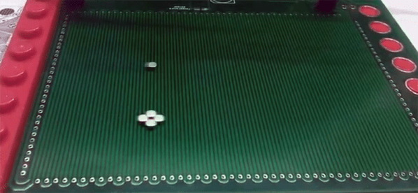
The latest build to show off the possibilities of motors etched on PCBs is [bobricius]’ micro manipulator. It’s a 100 mm square board capable of moving a small magnet around the surface. The point? Well, if you have to ask that question you’re really never going to get the point.
The design of this stepper motor is simply two coils of wire, with the X axis of the grid placed on the top copper layer of the PCB and the Y axis on the bottom copper layer. There are four poles to each of these coils, and they plug right into a standard stepper driver, so to control this board all you need is a basic Arduino and a motor shield. Or a RepRap board, take your pick, you probably have something sitting around in a junk drawer.
In the test of this board, the stepper motor can move small rare earth magnets around quickly and with high repeatability. As for what use this PCB stepper motor has, if you have to ask that question, you’ll never know. Also, because it looks cool.
Linux! Such a wonderful, rich, capable operating system has blessed us, and all for the low, low cost of absolutely free. It’s under the hood of countless servers, computers, phones, and embedded devices, and is the go-to solution for when you want to get the job done right. Why, then, does it curse me so?
Prologue
The penguin giveth, and the penguin taketh away.
My experience with the almighty penguin stretches back to the late 90s. Facebook hadn’t been invented yet, so most weekends were spent installing whatever came on the front of the latest computer mags. I wish I was kidding, but I’m really not.
Way back when, us kids would load the latest Red Hat or Fedora distribution onto our hand-me-down Pentium IIs, trying not to accidentally wipe our hard drive in the process. Limited to dial-up internet and very few help resources, it was pretty common that you’d spend hours watching progress bars tick over, only to wind up with no working mouse, or an X server that simply refused to start for man or God. Did I mention we did all this for fun?
Trying To Get Some Work Done
Of course, after growing up, real life and real responsibilities take over. Now, if I’m using Linux, it’s because I’ve got a job to do, not just because there’s nothing good to watch on Cartoon Network this weekend. I consider myself to be a fairly intermediate user. I’ve compiled a few things successfully, understood how to work with a variety of package managers, and once, just once, even managed to connect to a wireless network from the command line. There’s not a whole lot that phases me in this realm anymore.
For the past few years, I’ve been slowly working on a little rover by the name of TKIRV, powered by a Raspberry Pi. It was overdue for a camera upgrade, as I’d been using an old Microsoft webcam for far too long. I ordered a nice 1080p Raspberry Pi camera, and naturally the parts marinated in their boxes for a good couple of years. Finally, after much procrastination, I was eager to get my wheely boi back out on the road.
This was but the beginning my weekend slaying embedded Linux dragons.
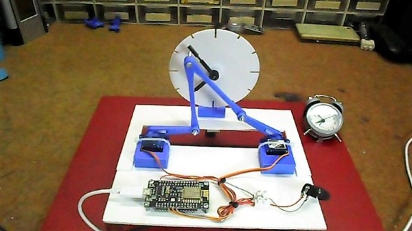
We see a lot of clocks here at Hackaday. Digital clocks, retro clocks, lots of Nixie clocks, binary clocks, and clocks that appear to be designed specifically to be unreadable. But this dual-servo kinematic clock is something we haven’t seen yet, and it’s certainly worth a mention.
[mircemk]’s idea is simple and hearkens back to grammar school days when [Teacher] put a large cardboard clock dial on the blackboard and went through the “big hand, little hand” drill. In this case, the static cardboard clock has been replaced by a 3D-printed dial and hands, while a pair of servos linked together by two arms takes the place of the teacher. The video below shows it in action; the joint in the linkage between the two servos has a screw sticking out that can be maneuvered across the clock face to reposition the hands. It’s a little jittery, though; [mircemk] might want to tune the servo loops up a bit or tighten the linkage joints to make things a little smoother.
Even with the shakes, we find it wonderfully weird and hard to stop watching. It reminds us a bit of this luminous plotting clock from a while back – same linkage, different display.
Regular readers will recognise this as the third part of a series exploring blacksmithing for those who have perhaps always fancied having a go but have never quite known where to start. It’s written from a position of the unusual experience of having grown up around a working forge, my dad may now be retired but he has a blacksmith specialising in architectural ironwork.
So far in this series we’ve looked in detail at the hearth and anvil that you might find in a typical forge, and delivered some pointers as to where you might look to find or even construct your own.Those are the signature pieces of equipment you’ll find in a forge, but with them alone you can still not be a blacksmith.
If I Had A Hammer…
An array of hammers of different weights and types.
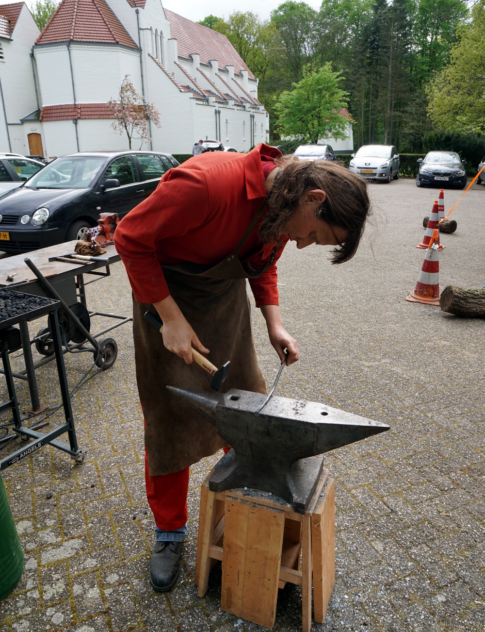
Given an anvil, a hearth, and a vat of water to quench hot work in, and you’re almost set for your forge, but not quite. Most of a modern blacksmith’s workshop is the standard metalworking assortment of welders and angle grinders, but there is a set of tools that remain essential for blacksmithing alone. Your hammers are what connect you to the work, and can be as individual as the preferences of the blacksmiths themselves. There is no “right” answer to the question of what hammer you should use, instead you should use the one that works best for you. I instinctively favour a round-faced ball-peen hammer because that’s what my dad mostly used, but for example my Dutch friends use square faced cross-peen hammers. Blacksmiths will often make their own hammers to suit their needs, for example my dad made more than one using the high-quality steel of vehicle half-shafts as a starting point. Hardening them is a specialist skill in its own right, and I remember quite a few experiments before he perfected it.
It may well be stating the obvious, but the weight of the hammer influences how much energy it can impart to the work, and in turn the size of work that can be done. Casting an eye over my dad’s hammers the three workaday weights were 2 pound, 3 pound, and 4 pound (roughly 1 kg, 1.5 kg, and 2 kg), allowing a variety from fine work to heavier hitting of larger pieces. In a recent project, making a mediaeval nail, I selected an unsubtle lump hammer to draw out the larger square stock, and a much smaller one to finish it up, create the fine point, and relatively thin head. These are only a subsection of the hammers at his disposal though, like most blacksmiths he has a variety for all tasks, up to sledgehammers. I have frequently taken my turn either holding a piece with tongs while he used a sledgehammer, or on the sledgehammer myself.
Tongs, for Hot Gripping Moments
A selection of tongs, including some designed for very specific tasks. Our thanks to [Igor Nikolic] for making this picture possible.The constant companion to a blacksmith’s hammer is a pair of tongs. These can be bought from blacksmith’s suppliers, but making a pair can be a task within the reach of most smiths. Two identical sides are made from pieces of stock, with long thin handles, a flat piece to form the hinge, and whatever jaw piece is required. It feels like cheating to form the hole for the hinge on a drill press rather than on the anvil with a punch, but riveting it with a short piece of bar is a straightforward enough process. Blacksmiths will have a huge array of tongs with different jaws for specific jobs, built up over years as jobs demand it. If you cast your mind back to the Finnish smith pictured halfway down the first installment of this series, you’ll find several racks of tongs. A later episode of this series will look at making a set of tongs, though we can’t promise in advance the quality of the finished article.
A final moment for today should be spent on the subject of protective equipment. The hazards of blacksmithing are relatively uncomplicated, but some basic protective clothing is still very much worth having. The most obvious hazard is heat, you will be working in a noisy environment with red hot metal and fire. Though you will generate fewer sparks than you’d expect, I have a blacksmith’s leather apron and a set of fire-resistant overalls. Both of these are readily available from blacksmith’s supply stores, and are well worth the investment. There are also a lot of heavy and sharp items involved, not to mention hot particles on the floor. For that reason I also have a set of steel-toecapped workboots rated for hot particles. They aren’t the most elegant of footwear, but they have saved me from a few nasty moments.
I do not have any face protection specifically for blacksmithing, but depending on the work in hand there may be some sparks created. A polycarbonate face shield rated for hot particles should be available from any safety equipment supplier, and shouldn’t cost too much, and is an essential thing to own if you are doing any grinding or rotary wire brushing. Beyond that, there are also leather gloves designed for handling hot metal. I don’t use them because I prefer the feel of the hammer directly and am happy to use a pair of tongs to hold hot pieces of steel.
We’ve taken you through the basic workshop equipment of a blacksmith over the last few episodes of this series, and you should now have a basic idea of the safety kit you would be well advised to own. From this foundation we’ll next take you into the forge and start looking at a few blacksmithing techniques and simple projects, and along the way we’ll see some of the materials involved, too.
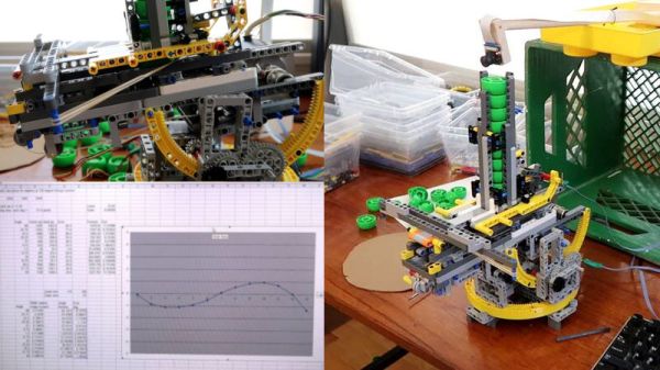
Before 3D printers, there was LEGO. And the little bricks are still useful for putting something together on the quick. Proof is YouTuber [Matthias Wandel]’s awesome bottle cap shooter build that uses rudimentary DIY computer vision to track you and then launch a barrage of plastic pieces at you.
This is an amazing project that has a bit of something for everyone. Lets start with the LEGO. [Matthias Wandel] starts with making a crossbow designed launcher and does an awesome job with showing us how it works in a video. The mechanism is an auto reloading and firing system that can be connected to a stepper motor. Next comes the pan and tilt mechanism which allows the turret to take better aim at moving targets: more LEGO and stepper motors.
The target tracker uses color matching in a program that curiously uses no OpenCV. It compares consecutive frame and then filters out red objects – the largest red dot is it. Since using a fisheye lens on the Raspbery Pi camera adds distortion, [Matthias Wandel] uses a jig made with more Legos to calibrate the image.
The final testing involved having his own child walk around the room being hunted but the autonomous machine. Kids do love toys even if they are trying to shoot bottle caps at them.


![A selection of tongs, including some designed for very specific tasks. Our thanks to [Igor Nikolic] for making this picture possible.](https://hackaday.com/wp-content/uploads/2019/04/tong-selection.jpg)