One of the joys of an itinerant existence comes in periodically being reunited with the fruits of various orders that were sent to hackerspaces or friends somewhere along the way. These anonymous parcels from afar hold an assortment of wonders, with the added element of anticipation that comes from forgetting exactly what had been ordered.
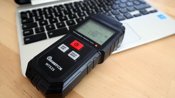
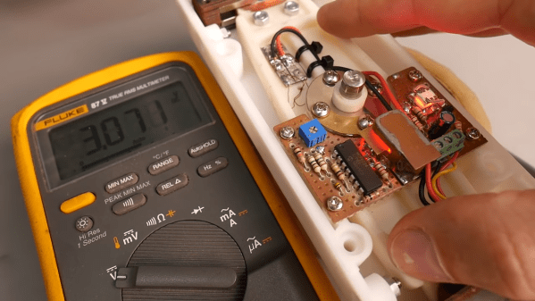
So it is with today’s subject, a Mustool MT525 electromagnetic radiation tester. At a cost not far above £10 ($13.70), this was an impulse purchase driven by curiosity; these devices claim to measure both magnetic and electric fields, but what do they really measure? My interest in these matters lies in the direction of radio, but I have never examined such an instrument. Time to subject it to the Hackaday treatment.
One of the most thrilling childhood toys for the adventurous 1970s or 1980s kid was probably the toy walkie-talkie. It didn’t matter that they were a very simple AM low-end-VHF radio with a range of about 500m and a Morse key of debatable utility, you could talk clandestinely with your friends, and be a more convincing spy, or commando, or whatever was the game of the moment. It’s a memory conjured up for grown-ups by [Chris G] with his ESP32 walkie-talkie, which replaces a shaky 49MHz connection with one a bit more robust through the magic of WiFi.
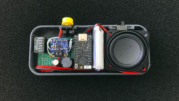
The hardware is a collection of modules on a custom PCB, aside from the ESP32 there’s an I2S microphone and I2S audio amplifier, which along with battery and speaker are housed in a neat 3D printed case. I2S is used for simplicity, but there is no reason why analogue components couldn’t be used with a few code changes. Connection is made via UDP over a WiFi network, or should there be no network via ESP-NOW. We’re not sure the range will be brilliant with those little on-board chip antennas, but with the wide range of 2.4GHz antennas to be had it’s likely a better result could easily be achieved if the stock item disappoints.
What do you do with a cool-looking misfit guitar that has non-working built-in effects and some iffy design aspects? Do you try to fix it and keep it original, or do you gut it and strut your stuff with new bits from around the shop? This is the conundrum that [Tim Sway] finds himself in with this late 70s/early 80s Formanta Solo II straight out of the USSR. (Video, embedded below.)
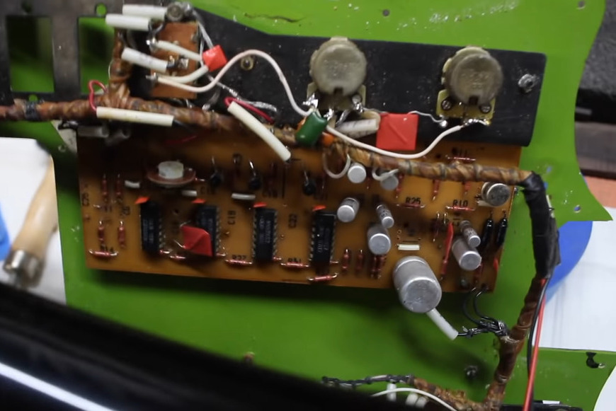
[Tim] likes a lot of things about it (and we do, too), especially the acid green pick guard, the sparkly pickups, and the beefy bridge that lets him set the string spacing individually, on the fly. It even has a built-in phaser and distortion, but those aren’t working and may never have worked that well at all.
The non-working effects guts.
As you can see in the video below, [Tim] has already spent a few hours making it playable and a little more palatable in order to figure out what to do with it electronics-wise. He started by making the 9 V compartment big enough to actually fit a battery inside, and drilled out bigger holes for new tuners.
Interestingly, these guitars had a 5-pin DIN receptacle instead of a 1/4″ jack. [Tim] bought an adapter just in case, but once someone dug up a schematic and sent it over, he decided to rewire it with a 1/4″.
For all of its plus sides, [Tim] doesn’t like the headstock on this thing at all and found the neck to be too chunky for the modern guitarist, so he cut down the headstock, shaved down the neck a bit, and stained it dark. He also made a new nut out of what looks like rosewood. Then it was on to the more standard stuff — file down the frets and polish them, oil the fretboard, and clean up the body.
The point of this exercise is to make a usable guitar for the modern musician. As [Tim] says, this is not a particularly valuable guitar, nor is it rare, and it wasn’t built that well to begin with. One of the issues is the switches — they’re kind of light and cheesy feeling, and one of them is directly in the strum path. Will [Tim] change those out but fix the original effects, or will he make the thing completely his own? We wait with bated breath.
Step one was to determine the frequency the fan’s remote used. Although public FCC records will reveal the frequency of operation, [River] thought it would be faster to use an inexpensive USB RTL-SDR with the Spektrum program to sweep the range of likely frequencies, and quickly found the fans speak 304.2 MHz.
Next was to reverse-engineer the protocol. Universal Radio Hacker is a tool designed to make deciphering unknown wireless protocols relatively painless using an RTL-SDR. [River] digitized a button press with it and immediately recognized it as simple on-off keying (OOK). With that knowledge, he digitized the radio commands from all seven buttons and was quickly able to reverse-engineer the entire protocol.
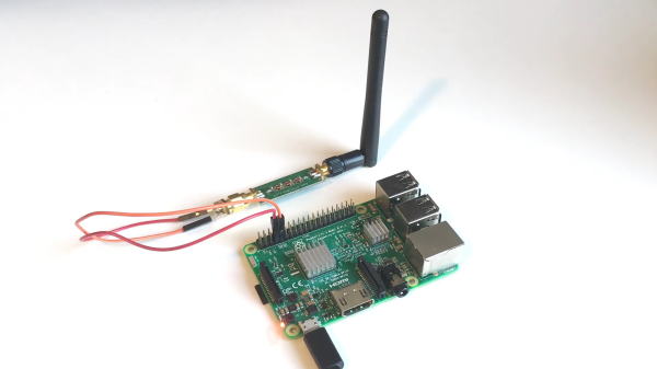
[River] wanted to use a Raspberry Pi to bring the fans into his home automation system, but the Raspberry Pi doesn’t have a 304.2 MHz radio. What it does have is user-programmable GPIO and the rpitx package, which converts a GPIO pin into a basic radio transmitter. Of course, the Pi’s GPIO pin’s aren’t long enough to efficiently transmit at 304.2 MHz, so [River] added a proper antenna, as well as a low-pass filter to clean up the transmitted signal. The rpitx package supports OOK out of the box, so [River] was quickly able get the Pi controlling his fan in no time!
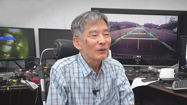
The notion of self driving cars isn’t new. You might be surprised at the number of such projects dating back to the 1920s. Many of these systems relied on external aids built into the roadways. It’s only recently that self driving cars on existing roadways are becoming closer to reality than fiction — increased computer processing power, smaller and power-efficient computers, compact Lidar and millimeter-wave Radar sensors are but a few enabling technologies. In South Korea, [Prof Min-hong Han] and his team of students took advantage of these technological advances and built an autonomous car which successfully navigated the streets of Seoul in several field trials. A second version subsequently drove itself along the 300 km journey from Seoul to the southern port city Busan. You might think this is boring news, until you realize this was accomplished back in the early 1990s using an Intel 386-powered desktop computer.
The project created a lot of buzz at the time, and was shown at the Daejeon Expo ’93 international exposition. Alas, the government eventually decided to cancel the research program, as it didn’t fit into their focus on heavy industries like ship building and steel production. Given the tremendous focus on self-driving and autonomous vehicles today, and with the benefit of hindsight, we wonder if that was the best choice. This isn’t the only decision from Seoul that seems questionable when viewed from the present — Samsung executives famously declined to buy Andy Rubin’s new operating system for digital cameras and handsets back in late 2004, and a few weeks later Android was purchased by Google.
You should check out [Prof Han]’s YouTube channel showing videos of the car’s camera while operating in various conditions and overlaid with the lane recognition markers and other information. I’ve driven the streets of Seoul, and that alone can be a frightening experience. But [Han] manages to stretch out in the back seat, so confident in his system that he doesn’t even wear a seatbelt.
[Leo Fernekes] has fallen down the Stirling engine rabbit hole. We mustn’t judge — things like this happen in the best of families, after all. And when they do happen to someone like [Leo], things can get interesting mighty quickly.
His current video, linked below, actually has precious little to do with his newfound Stirling engine habit per se. But when you build a Stirling engine, and you’re of a quantitative bent, having some way to measure its power output would be handy. That’s a job for a dynamometer, which [Leo] sets out to build in grand fashion. Dynos need to measure the torque and rotational speed of an engine while varying the load on it, and this one does it with style.
[Leo]’s torque transducer is completely DIY, consisting of hand-wound coils on the ends of a long lever arm that’s attached to the output shaft of the engine under test by a magnetic coupling. The coils are free to move within a strong magnetic field, with a PID loop controlling the current in the coils. Feedback on the arm’s position is provided by an optical sensor, also DIY, making the current necessary to keep the arm stationary proportional to the input torque. The video goes into great detail and has a lot of design and build tips.
We just love the whole vibe of this build. There may have been simpler or quicker ways to go about it, but [Leo] got this done with what he had on hand for a fraction of what buying in off-the-shelf parts would have cost. And the whole thing was a great learning experience, both for him and for us. It sort of reminds us of a dyno that [Jeremy Fielding] built a while back, albeit on a much different scale.
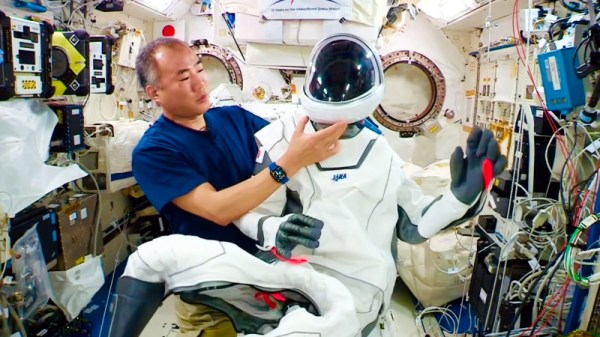
Beyond the fact that Hollywood costume designer Jose Fernandez was called in to develop its distinctively superhero look, SpaceX hasn’t released a lot of public information about their high-tech spacesuit. But thanks to Japanese astronaut [Soichi Noguchi], Mission Specialist on the first operational Crew Dragon flight and a current occupant of the International Space Station, we now have a guided tour of the futuristic garment. The fact that it was recorded in space is just an added bonus.
As it was released on his personal YouTube account and isn’t an official NASA production, the video is entirely in Japanese, though most of it can be understood from context. You can try turning on the automatic English translations, but unfortunately they seem to be struggling pretty hard on this video. For example as [Soichi] demonstrates the suit’s helmet, the captions read “A cat that is said to have been designed using a 3D printer.” Thanks, Google.
Still, this video provides us with the most information we’ve ever had about how astronauts store, wear, and operate the suit. [Soichi] starts by showing off the personalized bags that the suits are kept in and then explains how the one-piece suit opens on the bottom so the wearer can pull it on over their head. He also points out the three layers the suit is made of: a Teflon-coated outer shell, a fiber-reinforced core for strength, and an inner airtight garment.
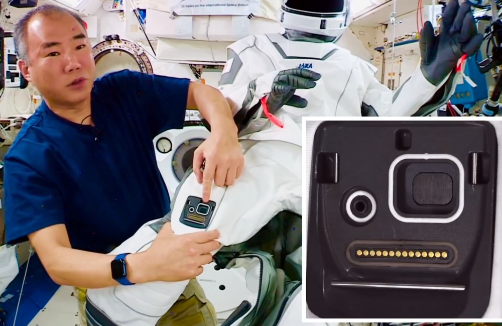
Little details are hidden all over the suit, such as a track built into the heel of the boot that’s used to restrain the astronaut’s feet to the Crew Dragon’s seats. [Soichi] also provides what appears to be the first public view of the umbilical connector on the suit. Hidden under a removable cover, the connector features 14-pins for data and power, a wide port for air circulation, and smaller high-pressure port for nitrox that would presumably be used to inflate the suit should the cabin lose pressure while in flight.