An LM386 Oscillator Thanks To Tungsten Under Glass

Once ubiquitous, the incandescent light bulb has become something of a lucerna non grata lately. Banned from home lighting, long gone from flashlights, and laughed out of existence by automotive engineers, you have to go a long way these days to find something that still uses a tungsten filament.

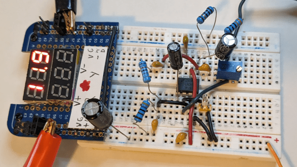
Strangely enough, this lamp-stabilized LM386 Wien bridge oscillator is one place where an incandescent bulb makes an appearance. The Wien bridge itself goes back to the 1890s when it was developed for impedance measurements, and its use in the feedback circuits of vacuum tube oscillators dates back to the 1930s. The incandescent bulb is used in the negative feedback path as an automatic gain control; the tungsten filament’s initial low resistance makes for high gain to kick off oscillation, after which it heats up and lowers the resistance to stabilize the oscillation.

For [Grug Huler], this was one of those “just for funsies” projects stemming from a data sheet example circuit showing a bulb-stabilized LM386 audio oscillator. He actually found it difficult to source the specified lamp — there’s that anti-tungsten bias again — but still managed to cobble together a working audio oscillator. The first pass actually came in pretty close to spec — 1.18 kHz compared to the predicted 1.07 kHz — and the scope showed a very nice-looking sine wave. We were honestly a bit surprised that the FFT analysis showed as many harmonics as it did, but all things considered, the oscillator performed pretty well, especially after a little more tweaking. And no, the light bulb never actually lights up.

Thanks to [Grug] for going down this particular rabbit hole and sharing what he learned. We love builds like this that unearth seemingly obsolete circuits and bring them back to life with modern components. OK, calling the LM386 a modern component might be stretching things a bit, but it is [Elliot]’s favorite chip for a reason.

Continue reading “An LM386 Oscillator Thanks To Tungsten Under Glass”

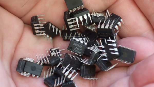
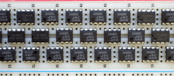
Hardware Hacker’s Marie Kondo: How Many LM386s Is Too Many?

We’re running a contest on Making Tech at Home: building projects out of whatever you’ve got around the house. As a hacker who’s never had a lab outside of my apartment, house, or hackerspace, I had to laugh at the premise. Where the heck else would I hack?

The idea is that you’re constrained to whatever parts you’ve got on hand. But at the risk of sounding like Scrooge McDuck sitting on a mountain of toilet paper, I’ve got literally hundreds of potentiometers in my closet, a couple IMUs, more microcontrollers than you can shake a stick at, and 500 ml of etching solution waiting for me in the bathroom. Switches, motors, timing belts, nichrome wire…maybe I should put in an order for another kilogram of 3D printer filament. In short, unless it’s a specialty part or an eBay module, I’m basically set.

But apparently not everyone is so well endowed. I’ve heard rumors of people who purchase all of the parts for a particular project. That ain’t me. The guru of household minimalism asks us to weigh each object in our possession and ask “does it spark joy?”. And the answer, when I pull out the needed 3.3 V low-dropout regulator and get the project built now instead of three days from now, is “yes”.

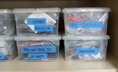
And I’m not even a hoarder. (I keep telling myself.) The rule that keeps me on this side of sanity: I have a box for each type of part, and they are essentially fixed. When no more motors fit in the motor box, no more motors are ordered, no matter how sexy, until some project uses enough of them to free up space. It’s worked for the last 20 years, long before any of us had even heard of Marie Kondo.

So if you also sit atop a heap of VFD displays like Smaug under the Lonely Mountain, we want to see what you can do. If you do win, Digi-Key is sending you a $500 goodie box to replenish your stash. But even if you don’t win, you’ve freed up space in the “Robot Stuff” box. That’s like winning, and you deserve some new servos. Keep on hacking!

This article is part of the Hackaday.com newsletter, delivered every seven days for each of the last 200+ weeks. It also includes our favorite articles from the last seven days that you can see on the web version of the newsletter.

Want this type of article to hit your inbox every Friday morning? You should sign up!

You Can Have My LM386s When You Pry Them From My Cold Dead Hands

Everyone has a chip-of-shame: it’s the part that you know is suboptimal but you keep using it anyway because it just works well enough. Maybe it’s not what you would put into a design that you’re building more than a couple of, but for a quick and dirty lashup, it’s just the ticket. For Hackaday’s [Adam Fabio], that chip is the TIP120 transistor. Truth be told, we have more than one chip of shame, but for audio amplification purposes, it’s the LM386.

The LM386 is an old design, and requires a few supporting passive components to get its best performance, but it’s fundamentally solid. It’s not noise-free and doesn’t run on 3.3 V, but if you can fit a 9 V battery into your project and you need to push a moderate amount of sound out of a speaker, we’ll show you how to get the job done with an LM386.

Continue reading “You Can Have My LM386s When You Pry Them From My Cold Dead Hands”

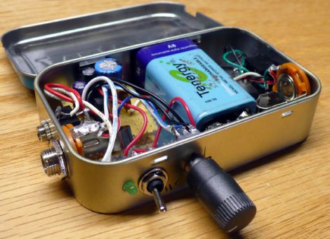
LM386 Altoids Tin Amp

altoids_amp

Hacker [Dino Segovis] is back again with the fifth installment in his “Hack a Week” series. This time around he has put together a 1/2 watt audio amplifier that would make for a great weekend project. He’s a big fan of the LM386 amplifier chip because it does so much in such a small package. Since it is so versatile, he used it as the centerpiece of his Altoids tin amplifier.

Now an audio amp inside an Altoids tin isn’t exactly a new concept, but [Dino] takes the time to discuss the circuit in detail, which is great for any beginners out there who are looking for a fun and relatively easy project. After a high-speed video of the assembly process he walks us through the completed amp, then treats us to a couple of short demos.

One thing that makes his amp different than others we have seen in the past is the addition of a 1/4” guitar jack, which allows him to use his amplifier as a combo amp/distortion effect box.

It’s another job well done, so be sure to keep reading if you’d like to watch the latest Hack a Week episode in its entirety.

Continue reading “LM386 Altoids Tin Amp”

DIY Walkie-Talkie With ESP32 And ESP-NOW

In a recent article in Elektor magazine, [Clemens Valens] describes the construction and software for an ESP32 walkie-talkie system that uses ESP-NOW for the wireless connection between units, along with a low-cost condenser microphone with a transistor-based preamplifier and an LM386 op-amp for the speaker circuit. In the ESP32 module the built-in DAC and ADC are used for audio in and output, which provide just about enough resolution for voice communication.

So why use ESP-NOW rather than WiFi or Bluetooth? Mostly because of range, power usage and convenience with no SSIDs and passwords to bother with.

The DIY Walkie-Talkie circuit diagram. (Credit: Clemens Valens, Elektor magazine)

ESP-NOW is Espressif’s own network protocol that uses the same underlying hardware as 2.4 GHz WiFi and Bluetooth, but focuses on more basic direct and mesh-style communication. It can be considered to be somewhat like low-level UDP with MAC address instead of IP address, which makes it useful for fire-and-forget traffic such as from IoT devices.

In the past, we’ve seen ESP-NOW control everything from fake security cameras to CNC machines. In fact, we’ve even seen it used in another walkie-talkie a couple years back.

Wien Bridge Oscillator Drives Distortion Into The Floor

It’s not often that a single photo can tell you pretty much everything you need to know about a project, but the spectrum analyzer screenshot nearby is the perfect summary of this over-the-top low-distortion audio oscillator build. But that doesn’t mean there’s not a ton of interesting stuff going on with this one, so buckle up.

One spike at the fundamental and not much more.

The project is by [Basin Street Design], who doesn’t really offer much by way of inspiration for this undertaking, nor a discussion on what this will be used for. But the design goals are pretty clear: build an oscillator with as little distortion as possible across the audio frequency range.

The basic circuit is the well-known Wien bridge oscillator where the R-C pairs are switched in and out of the feedback loop to achieve frequency range control. This was accomplished with rotary switches rebuilt from their original configuration in a Heathkit IG-18 sine/square wave generator, a defunct instrument that was gutted and used as an enclosure for this build. There are a lot of other treats here, too, like the automatic gain control (AGC) that uses a homebrew voltage-controlled resistor made from an incandescent lamp and a cadmium sulfide photoresistor glued inside a piece of brake line, and an output attenuator made from discrete resistors that drops the output in 10 dB steps while maintaining an overall 75-Ohm impedance.

But at the end of the day, it all comes down to that single spike on the spectrum analyzer, with no apparent harmonics. To make sure there wasn’t something hiding down in the noise, [Basin Street] added a notch filter to lower the fundamental by 60 dB, allowing the spectrum analyzer sensitivity to be cranked way up. Harmonics were visible, but so far down into the noise — as low as -115 dBc — that it’s hardly worth mentioning.

There’s a lot more detail in this one, so dive in and enjoy. If you want another take on Wien bridge circuits, check out this recent LM386-based oscillator. Just don’t expect such low distortion with that one.

Breadboarding A Game Boy From Scratch

The original Nintendo Game Boy is a stout piece of hardware in a solid plastic enclosure. [Raphael Stäbler] recreated the popular handheld on a breadboard instead, in a fully-functional way, to boot.

[Raphael]’s build doesn’t rely on a real Game Boy CPU or components. Instead it’s emulated with the aid of a Teensy 4.1 microcontroller. [Raphael] coded up an emulator from scratch, instruction by instruction, something he’s documented on his own blog. The Teensy is placed on a breadboard, and hooked up with a series of 8 buttons to serve as the controls. Audio output is via a LM386 acting as a simple audio amp, hooked up with an original Game Boy speaker for more authentic sound. Display is thanks to a FT81x display driver running a small LCD. Games are loaded via an SD card formatted in the FAT32 file system.

While it’s not as ergonomic as the original Nintendo console, it works, and works well! It’s an impressive project to see the Game Boy recreated from scratch inside a powerful microcontroller. We’ve seen other projects go to similar lengths before. Video after the break.

Continue reading “Breadboarding A Game Boy From Scratch”