OpenDog: Adding Force Sensitive Feet

[James Bruton] OpenDog remains one of the most impressive home-built robotics projects we’ve seen here on Hackaday, and it’s a gift that just keeps on giving. This time he’s working on adding force sensing capabilities to OpenDog’s legs to allow for more dynamic movement control.

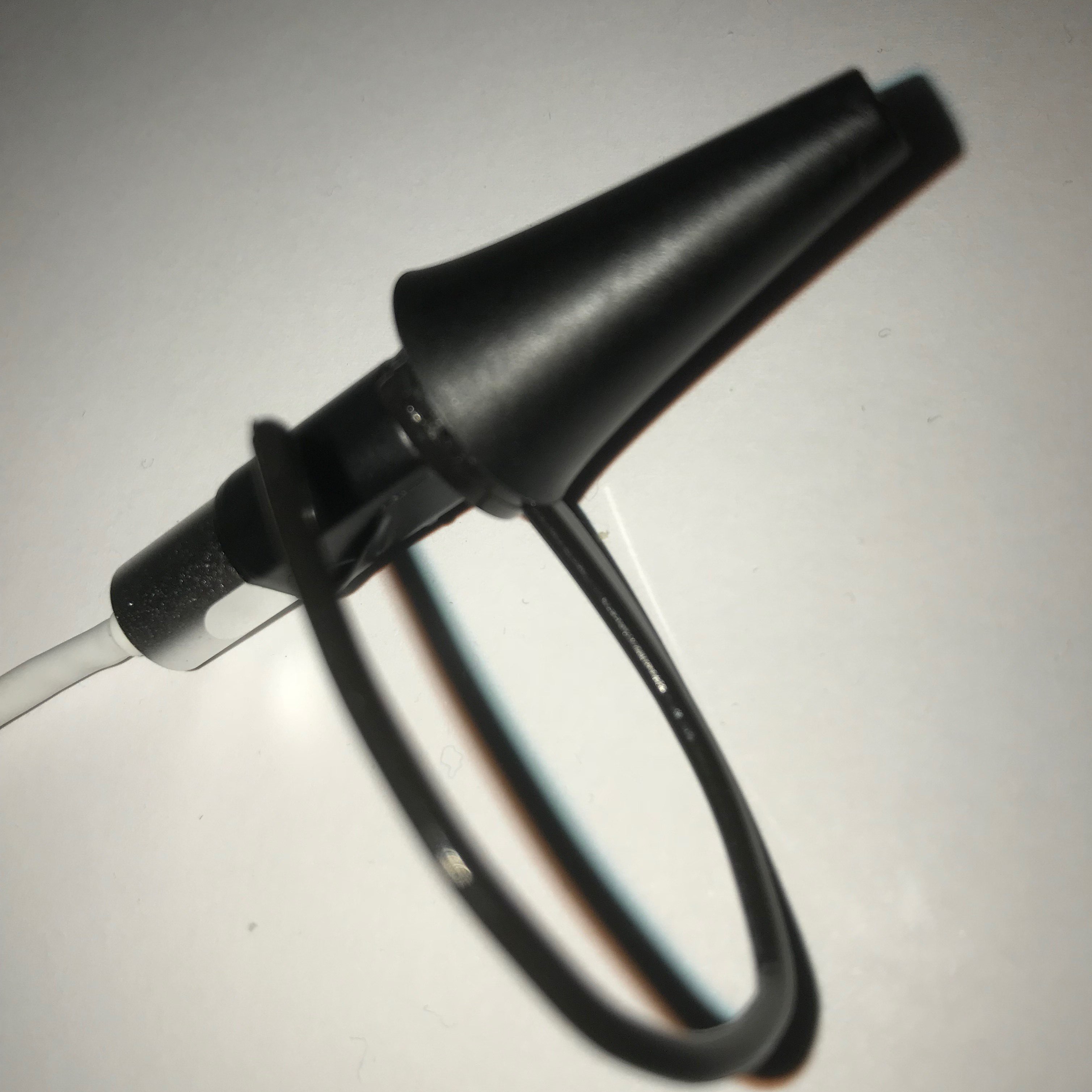
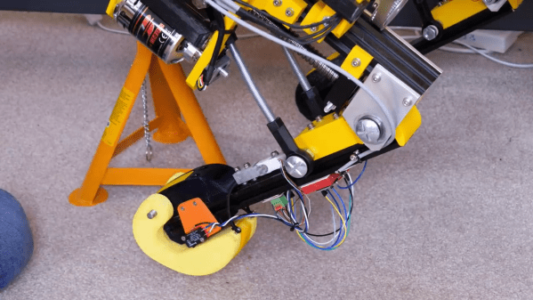
The actuators in the legs are three-phase outrunner motors that drive ball-screws via a belt. This configuration is non-backdrivable, meaning the legs cannot be moved when an external force is, which could lead to mechanical failures. He as tested other backdrivable leg configurations with other robots, but did not want to rebuild OpenDog completely. The solution [James] went with is a redesigned foot with an inbuilt switch, to confirm that the foot is touching the ground, and a load cell attached in the middle of the bottom leg segment. The load cell is bolted rigidly onto the leg segment, which allows it to sense when the leg is carrying load, without damaging the load cell itself.

Unfortunately all the serial ports on OpenDog’s main Teensy 3.6 controller are already used, so he converted the signal from the load cell to PWM, to allow it to be read by a normal GPIO pin. This works well in isolation, but when [James] switches on the motors, the PWM signal from the load sensor gets flooded by interference, making it unreadable. To solve this problem, he wants to implement a CAN bus, which will allow for more inputs and outputs and hopefully solve the interference problem. However, [James] has no experience with the CAN protocol, so learning to use it is going to be a project on its own.

OpenDog is turning into a very lengthy, time-consuming project, [James] says that the lessons learned from it have been invaluable for a number of other projects. This is something to keep in mind with everything we tackle. Choose projects were the experience gained and/or relationships developed are worth it on their own, even when the project fails in a conventional sense. This way you can never really lose.

Assistive Technolgy Switch Is Actuated Using Your Ear Muscles

Assistive technology is extremely fertile ground for hackers to make a difference, because of the unique requirements of each user and the high costs of commercial solutions. [Nick] has been working on Earswitch, an innovative assistive tech switch that can be actuated using voluntary movement of the middle ear muscle.

Most people don’t know they can contract their middle ear muscle, technically called the tensor tympani, but will recognise it as a rumbling sound or muffling effect of your hearing when yawning or tightly closing eyes. Its function is actually to protect your hearing from loud sounds screaming or chewing. [Nick] ran a survey and found that 75% can consciously contract the tensor tympani and 17% of can do it in isolation from other movements. Using a cheap USB auroscope (an ear camera like the one [Jenny] reviewed in November), he was able to detect the movement using iSpy, an open source software package meant for video surveillance. The output from iSpy is used to control Grid3, a commercial assistive technology software package. [Nick] also envisions the technology being used as a control interface for consumer electronics via earphones.

With the proof of concept done, [Nick] is looking at ways to make the tech more practical to actually use, possibly with a CMOS camera module inside a standard noise canceling headphones. Simpler optical sensors like reflectance or time-of-flight are also options being investigated. If you have suggestions for or possible use case, drop by on the project page.

Assistive tech always makes for interesting hacks. We recently saw a robotic arm that helps people feed themselves, and the 2017 Hackaday Prize has an entire stage that was focused on assistive technology.

Folding An Off-The-Shelf 3D Printer

Most 3D printers don’t take up a lot of space, but they can be pretty bulky and awkward to travel with. [Jón Schone] needed a compact folding 3D printer for a secret project on his YouTube channel ProperPrinting, so he decided to modify a Creality Ender 3 Pro to achieve this.

Starting with a brand new Ender 3 Pro, and his first steps were to move the display and power supply unit into the bottom frame to make space for the folding top frame. For the folding mechanism, he settled on a four bar linkage that allows the vertical frame to translate to the front of the printer as it folds down, which lets it become a really compact package with minimal wasted space. The joints consist of fitting 3D printed in carbon fibre reinforced nylon, with bolts for shafts. The entire mechanism is made adjustable for fine-tuning by using threaded rod and sliding mounting points on the extruded frame. Small brackets on each side of the frame allows the printer to snap securely into both its upright and folded positions.

All in all we think this is well-designed and beautifully executed hack, enough to make us really want to build one for ourselves. It will remain to be seen if any slop develops with repeated folding and use, especially at the snap-in end stops, but that should still be an easy fix if it happens.

We’ve previously featured [Jón]’s custom 3D printed D-sub connectors, also for his Ender 3. Also check out another folding printer, the X-printer.

Continue reading “Folding An Off-The-Shelf 3D Printer”

Quadruped Robot Disguises Itself As A Ball

When the Skynet baseball bot swarms attack, we’ll be throwing [Carl Bugeja] some dirty looks for getting them started. He’s been working on 4B, a little quadruped robot that can transform itself into a sphere almost perfectly.

Before [Carl] was distracted by the wonders of PCB actuators more than a year ago, he started working on this little guy. He finally found some time to get it moving on its own, and the preliminary results look promising to say the least. Inside the 6 cm sphere is a total of 12 servos, 3 for each leg. All of the mechanical parts were 3D printed in nylon on an SLS machine, and the custom PCB has a BLE microcontroller module, an IMU and IR proximity sensors onboard. Everything is open source with all the files available on the Hackaday.io project page.

The microcontroller runs a full inverse kinematic model, so only the desired tip and base coordinate for each leg is input and the servo angles are automatically calculated. Ultimately [Carl] aims to have the robot both walking and rolling controllably. So far he’s achieved some degree of success in both, but it still needs some work (see the videos below. We’re eager to see what the future holds for this delightfully creepy bot.

Walking robots are always an interesting challenge. For more of our future overlords, check out this adorable little cat and this truly terrifying strandbeest.

DIY Electric Roller Bender Can Handle The Thick(er) Stuff

Every serious metal worker will end up getting themself a roller bender at some point, but if you’re as dedicated as [Meanwhile in the Garage], you might just start building the things yourself. His heavy-duty electric roller bender, demonstrated in the video after the break, is perfect for the thicker steel and bigger radii his smaller manual machine can’t handle.

The basic concept is the same in both machines, with two fixed rollers and a third adjustable opposing one between them. Most of the components are pieces of scrap metal, and each shaft runs on bearings mounted in homemade pillow blocks. The two fixed shafts are connected together by a chain drive, and a scrap industrial motor provides the rotating power through a worm gearbox.  There are two adjustable bushings on each shaft to keep the work piece aligned. The lead screw from an old car jack is used to adjust the position of the moving roller.

We picked up a few interesting tips from the video, like how to properly align a cylindrical workpiece in a drill press for drilling radial holes.  He also used toggle switches as limit switches in a pretty ingenious way, and F-clamps on the work piece to activate them when it reaches the end.

Building your own tools at home is a time-honoured hacking tradition, which we have never seen a shortage of here on Hackaday. Check out this DIY drill press and vertical CNC mill.

Autonomous Boat For Awesome Video Hyperlapses

With the ever-increasing capabilities of smart phones, action cameras, and hand-held gimbals, the battle for the best shots is intensifying daily on platforms like YouTube and Instagram. Hyperlapse sequences are one of the popular weapons in the armoury, and [Daniel Riley] aka [rctestflight] realised that his autonomous boat could be an awesome hyperlapse platform.

This is the third version of his autonomous boat, with version 1 suffering from seaweed assaults and version 2 almost sleeping with the fishes. The new version is a flat bottomed craft was built almost completely from pink insulation foam, making it stable and unsinkable. It uses the same electronics and air boat propulsion as version 2, with addition of a GoPro mounted in smart phone gimbal to film the hyper lapses. It has a tendency to push the bow into the water at full throttle, due to the high mounted motors, but was corrected by adding a foam bulge beneath the bow, at the cost of some efficiency.

Getting the gimbal settings tuned to create hyperlapses without panning jumps turned out to be the most difficult part. On calm water the boat is stable enough to fool the IMU into believing that it’s is not turning, so the gimbal controller uses the motor encoders to keep position, which don’t allow it to absorb all the small heading corrections the boat is constantly making. Things improved after turning off the encoder integration, but it would still occasionally bump against the edges of the dead band inside which the gimbal does not turn with the boat. In the end [Daniel] settled for slowly panning the gimbal to the left, while plotting a path with carefully calculated left turns to keep the boat itself out of the shot. While not perfect, the sequences still beautifully captured the night time scenery of Lake Union, Seattle. Getting it to this level cost many hours of midnight testing, since [Daniel] was doing his best to avoid other boat traffic, and we believe it paid off.

We look forward to his next videos, including an update on his solar plane. Continue reading “Autonomous Boat For Awesome Video Hyperlapses”

Open Source $50 Water Turbine From Repurposed Parts

Easy access to reliable electrical power is something a lot of us take for granted, but in developing countries or after natural disaster, it can be a rare commodity. [Daniel Connelly] has been working hard to develop infrastructure people can build themselves, and his latest project is a 200 W water turbine (video after the break) that can be built for about $50.

The core of the system is a wheel and motor from a hoverboard. What looks like 110 mm PVC tubing is connected together in a U-shape that can be mounted over the wall of a man-made channel. The inlet side is shorter than the outlet, and the system must be filled with water to allow the flow to start, like a siphon. The first two versions had the impeller sitting on the end of the outlet tube. V1 used a scrap plastic radial impeller of unknown origin, and did not work at all. V2 had a 3D printed impeller that worked pretty well, but the rotation speed wasn’t high enough to produce the voltage that [Daniel] wanted.

V3 used a large computer fan that was mounted in the short horizontal piece of section of tubing at the top of the system. It worked spectacularly well, producing about 55 V AC over a single phase of the motor, which should hopefully end up producing about 90 V DC and 200-500 W after rectifying the 3-phase motor output. This only however indicative, we would really like to see it tested with different loads connected. The output will also be dependent on the flow rate and head pressure of a particular stream/channel/river, and [Daniel] admits that they had pretty much ideal conditions for their tests. If hoverboard motors are hard to come by, a motorcycle alternator should also work well.

[Daniel] is still working out the kinks of the system, but as with his other designs on OpenSourceLowTech he will release the full open source design and tutorials as soon as he is ready. We are looking forward to seeing the system implemented out in the wild. For off-grid power, home built and 3D printed wind generators are another popular topic around here, if you don’t have a handy channel nearby.

Continue reading “Open Source $50 Water Turbine From Repurposed Parts”