As an introduction to embedded electronics and programming in a straightforward environment, there isn’t much out there that can hold a torch to the Arduino Uno. Cheap (especially if you count the clones), easy to find, and quick to deploy, with countless support libraries, it’s a go-to for many a hack. This scribe simply can’t remember how many he’s bought, hacked, and deployed over the years. But can it be improved? [John Loeffler] thinks so, and his 2023 Hackaday Prize entry, the Uno Plus+ could be the one.
If this is too much bling for you, there is a version with LEDs adjacent to non-illuminated headers.
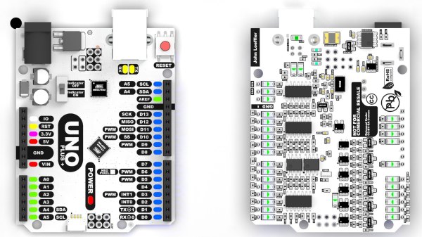
After clearing the top deck of extraneous components (by shoving them on the bottom) there was much more space to expand the header labeling, so there can be no accidental misplacement of those DuPont wires this thing will inevitably sprout randomly.
The board also has an additional Stemma/Qwiic connector and a Neopixel LED for indication duties. Also sitting on the PCB bottom are a ton of opamps, to drive the header indicators. Yes, this board has a full set of colour-coded LED bling indicators, showing the logical state of each and every pin on all headers, giving an easy way to check the desired activity is occurring. Plus it looks cool. Illuminated headers? YES!
Think the Uno too light on resources to perform any meaningful modern workloads? Think again!
Of all the high-tech medical gadgets we read about often, the Magnetic Resonance Imaging (MRI) machine is possibly the most mysterious of all. The ability to peer inside a living body, in a minimally invasive manner whilst differentiating tissue types, in near real-time was the stuff of science fiction not too many years ago. Now it’s commonplace. But how does the machine actually work? Real Engineering on YouTube presents the Insane Engineering of MRI Machines to help us along this learning curve, at least in a little way.
Both types of gradient coil are stacked around the subject inside the main field coil
The basic principle of operation is to align the spin ‘axis’ of all the subject’s hydrogen nuclei using an enormous magnetic field produced by a liquid-helium-cooled superconducting electromagnet. The spins are then perturbed with a carefully tuned radio frequency pulse delivered via a large drive coil.
After a short time, the spins revert back to align with the magnetic field, remitting a radio pulse at the same frequency. Every single hydrogen nucleus (just a proton!) responds at roughly the same time, with the combined signal being detected by the receive coil (often the same physical coil as the driver.)
Time taken for the perturbed spin to return to magnetic alignment
There are two main issues to solve. Obviously, the whole body section is ‘transmitting’ this radio signal all in one big pulse, so how do you identify the different areas of 3D space (i.e. the different body structures) and how do you differentiate (referred to as contrast) different tissue types, such as determine if something is bone or fat?
By looking at the decay envelope of the return pulse, two separate measures with different periods can be determined; T1, the spin relaxation period, and T2, the total spin relaxation period. The first one is a measure of how long it takes the spin to realign, and the second measures the total period needed for all the individual interactions between different atoms in the subject to settle down. The values of T1 and T2 are programmed into the machine to adjust the pulse rate and observation time to favor the detection of one or the other effect, effectively selecting the type of tissue to be resolved.
Time taken for the relative phasing inside a tissue locality to settle down to the same average spin alignment
The second issue is more complex. Spatial resolution is achieved by first selecting a plane to virtually slice the body into a 2D image. Because the frequency of the RF pulse needed to knock the proton spin out of alignment is dependent upon the magnetic field strength, overlaying a second magnetic field via a gradient coil allows the local magnetic field to be tuned along the axis of the machine and with a corresponding tweak to the RF frequency an entire body slice can be selected.
All RF emissions from the subject emanate from just the selected slice reducing the 3D resolution problem to a 2D problem. Finally, a similar trick is applied orthogonally, with another set of gradient coils that adjust the relative phase of the spins of stripes of atoms through the slice. This enables the use of a 2D inverse Fourier transform of multiple phase and frequency combinations to image the slice from every angle, and a 2D image of the subject can then be reconstructed and sent to the display computer for the operator to observe.
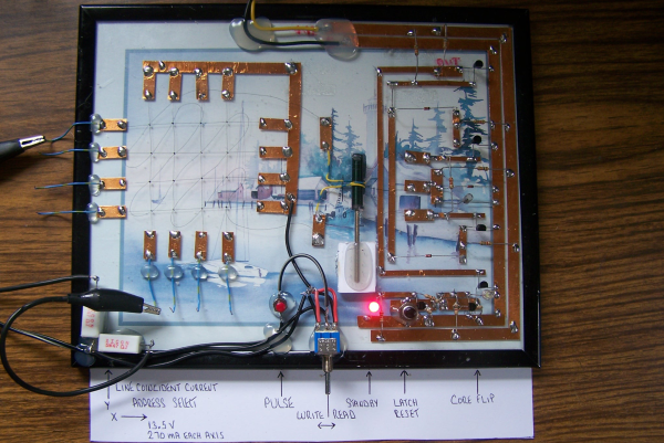
No matter how memory technology marches on, magnetic core memory is still cool. Radiation-hard, nonvolatile, and so pretty. What’s there not to love? [Mark Nesselhaus] is no stranger to fun in-your-face electronics builds — judging from his hackaday.io projects — and this entry to the Hackaday Op-Amp contest is no outlier. This is a sixteen-bit magnetic core RAM demonstrator built upon glass using copper tape and solder, which always looks great and is actually not all that hard to do yourself provided you grab a new scalpel blade from the pack before starting.
Transformer-coupled differential front-end amplifier driving an SR latch.
For the uninitiated, the crossed X and Y wires each host a hard magnetic toroid which can only be magnetised by a field beyond a certain threshold due to the shape of the B-H curve of ferrite materials. The idea is for a required threshold current, drive the selected X line and Y line each with a current half of this value, so that only the selected core bit ‘sees’ the full field value, and flips state. This means that only a single bit can be written for each core plane, so to form longer words these layers are stacked, producing some wonderful cubic structures. These magnetic circuits are responsible for putting a human on the moon.
Reading the bit state is basically the opposite. A third sense wire is passed sequentially through each bit in the array. By driving a current the opposite way through the selected core bit, if the core was previously magnetised then the sense wire will read a short pulse that can be amplified and registered. The eagle-eyed will realise that reading is a destructive process, so this needs to be followed up by a write-back process to refresh the bit, although the core state will persist without power, giving the memory nonvolatile behaviour.
[Mark] utilises a simple discrete transistor differential transformed-coupled front end which senses the tiny current pulse and passes it along to a Set-Reset latch for visualisation. This simple concept could easily be extended to make this a practical memory, but for now, addressing is courtesy of a pair of crocodile clips and a discrete write/read pulse switch. We will watch with interest how far this goes.
DIY core memory builds are not a regular occurrence around these parts, but we see them from time to time, like this polished 64-bit setup. Core arrays are not the only magnetic memory in town, we’ve also seen DIY core rope memories as well.
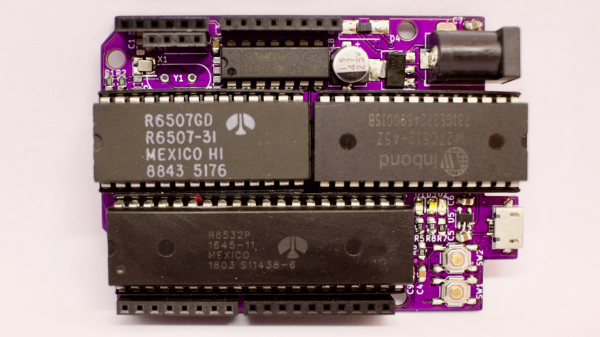
[Anders Nielsen] presents his entry for the 2023 Hackaday Prize: The 65uino. Which as you might be able to guess, is a 6502-based microcomputer wedged into an Arduino Uno form factor (well, almost wedged in, but we’ll let it slide) The premise is simple, older micros are easier to understand, the board can be build up from new-old or salvaged stock, and that’s more chips on boards and less sitting on a dusty shelf. After all, even though the 6502 in its original form is long obsolete, it’s far better to be pushing some electrons around, than sitting there decaying.
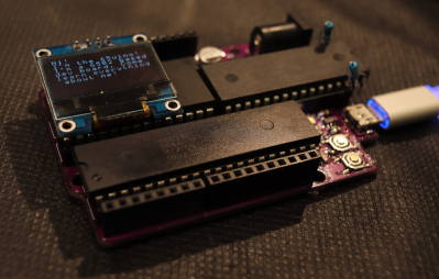
The OLED frame buffer is bigger than the host’s entire RAM. No problem!
From an educational perspective, the first lesson is the hand-soldering of through-hole DIP components and a smattering of straightforward surface mount parts in their supporting roles. Then on to setting up the cc65 toolchain. To say this is a pure 6502 system is a little misleading, it actually uses the 6507 device variant, which is a die-bond variant of the same device but with only 28 of the pins utilized.
The use of the 6532 RIOT (RAM-I/O-Timer) chip provides two 8-bit ports of GPIO as well as a timer and 128 bytes of SRAM, making the design more compact. There is a socket that will accept a 24 or 28-pin E(E)PROM device, with the extra four pins removable and the PCB snapped off if fitment into a standard ‘Uno case is desirable. Neat!
Full hardware build and PCB design (using KiCAD) are available on the 65uino GitHub page. Just remember folks, with everything minimal 6502 related — some assembly required :D
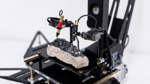
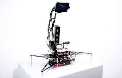
Well, noises anyway. [Dmitry Morozov] and [Alexandra Gavrilova] present an interesting electronics-based art installation, which probes a large chunk of crystalline magnetite, using a pair of servo-mounted probes, ‘measuring’ the surface conductivity and generating some sound and visuals.
It appears to have only one degree of freedom per probe, so we’re not so sure all that much of the surface gets probed per run, but however it works it produces some interesting, almost random results. The premise is that the point-to-point surface resistivity is unpredictable due to the chaotically formed crystals all jumbled up, but somehow uses these measured data to generate some waveshapes vaguely reminiscent of the resistivity profile of the sample, the output of which is then fed into a sound synthesis application and pumped out of a speaker. It certainly looks fun.
From a constructional perspective, hardware is based around a LattePanda fed samples by an ADS1115 ADC, which presumably is also responsible for driving the LCD monitor and the sound system. An Arduino is also wedged in there perhaps for servo-driving duty, maybe also as part of the signal chain from the probes, but that is just a guess on our part. The software uses the VVVV (Visual Live-programming suite) and the Pure Data environment.
This Hackaday prize entry from [saul] is the beginning of a reconfigurable kit of 3D printed parts and servo motors for robotics learning. With just access to a printer, a few cheap-as-chips servo motors, an Arduino, and some nuts and bolts, you could be hacking together robot walkers within a few hours of starting!
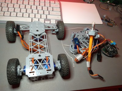
Bolt Bots is very simple to understand, with all the mechanics and wiring out there in the breeze, but strictly for indoor use we reckon. If you want to add remote control to your application, then drop in one of the ubiquitous nRF24L01 boards and build yourself a copy of the remote control [saul] handily provides in this other project.
There really isn’t a great deal we can say about this, as it’s essentially a build kit with quite a few configuration options, and you just have to build with it and see what’s possible. We expect the number of parts to proliferate over time giving even more options. So far [saul] demonstrates a few flavors of ‘walkers’, a rudimentary ‘robot arm’, and even a hanging drawbot.
The bolt hardware can be found in this GitHub repo, and the remote control code in this second one.
Servo-based designs are sometimes sneered at due to their dubious accuracy and repeatability, but with a little of effort, this can be vastly improved upon. Also, multi-legged walkers need multiple servos and controllers to drive ’em. Or do they?
ARCTOS is a 6-DOF robot arm based upon 3D printed mechanics running a modified version of GRBL firmware. Let’s get this straight now, the firmware is open source, but the hardware plans are a paid download, but for less than forty euros, we reckon the investment would be well worth it, judging from the quality of the build instructions and the software support already in place. Continue reading “Arctos Robotics: Build A Robot Arm Out Of 3D Printer Spares?”→


 probed per run, but however it works it produces some interesting, almost random results. The premise is that the point-to-point surface resistivity is unpredictable due to the chaotically formed crystals all jumbled up, but somehow uses these measured data to generate some waveshapes vaguely reminiscent of the resistivity profile of the sample, the output of which is then fed into a sound synthesis application and pumped out of a speaker. It certainly looks fun.
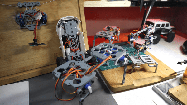
 nRF24L01 boards and build yourself a copy of the remote control [saul] handily provides in