Two-Key Keyboard Build Log Starts Small, But Thinks Big

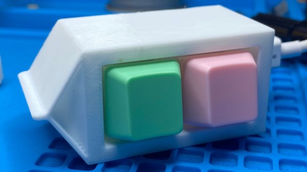
Interested in making a custom keyboard, but unsure where to start? Good news, because [Jared]’s build log for an adorable “2% Milk” two-key mini-keyboard covers everything you need to know about making a custom keyboard, including how to add optional RGB lighting. The only difference is that it gets done in a smaller and cheaper package than jumping directly in with a full-size DIY keyboard.

[Jared] is definitely no stranger to custom keyboard work, but when he saw parts for a two-key “2% Milk” keyboard for sale online, he simply couldn’t resist. Luckily for us, he took plenty of photos and his build log makes an excellent tutorial for anyone who wants to get into custom keyboards by starting small.

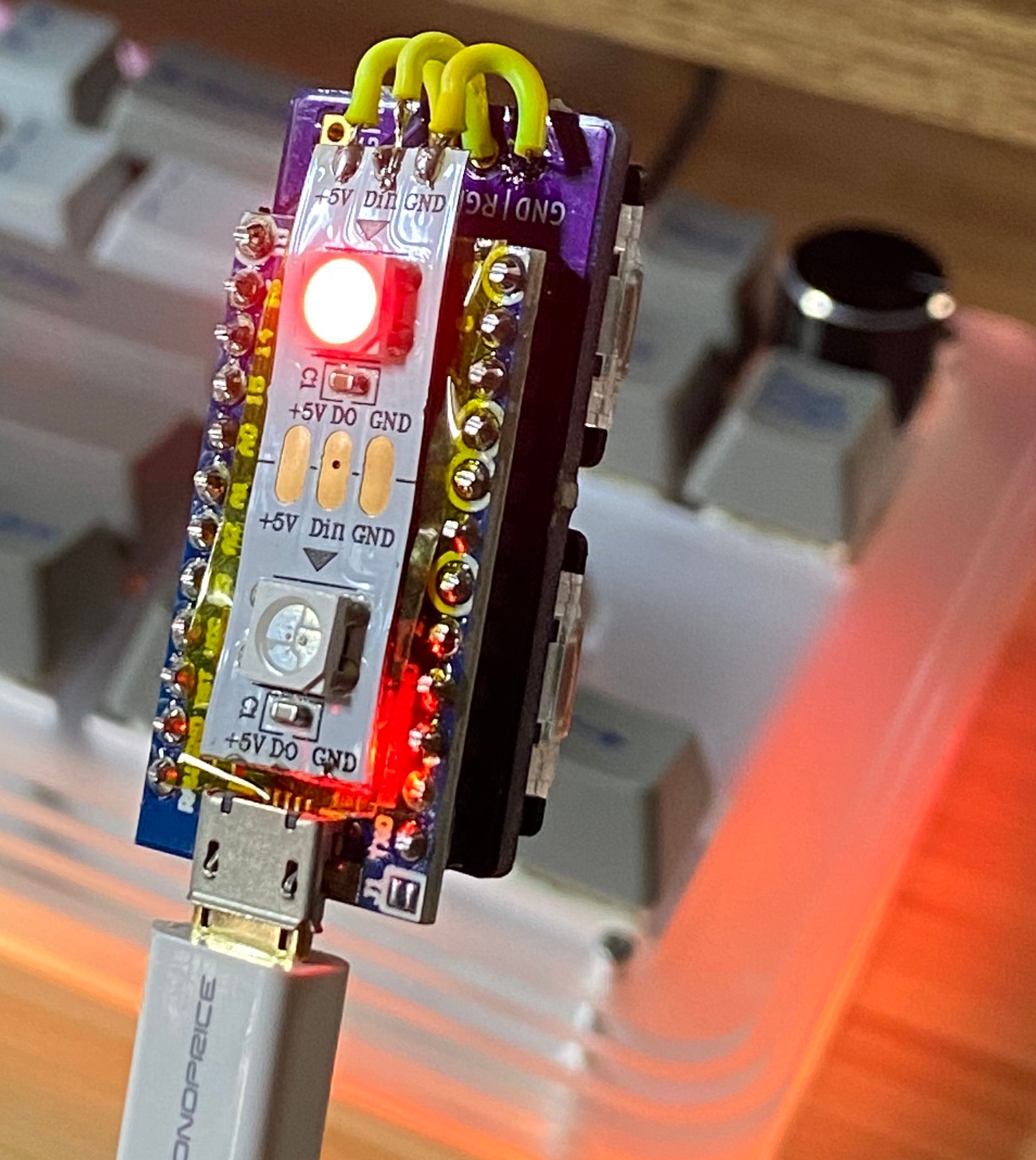
The hardware elements are clear by looking at photos, but what about the software? For that, [Jared] uses a Teensy  Pro Micro clone running QMK, an open source project for driving and configuring custom input devices. QMK drives tiny devices like the 2% Milk just as easily as it does larger ones, so following [Jared]’s build log therefore conveys exactly the same familiarity that would be needed to work on a bigger keyboard, which is part of what makes it such a great project to document.

Interested in going a little deeper down the custom keyboard rabbit hole? You can go entirely DIY, but there’s also no need to roll everything from scratch. It’s possible to buy most of the parts and treat the project like a kit, and Hackaday’s own [Kristina Panos] is here to tell you all about what that was like.

Fixing NRF24L01+ Modules Without Going (Too) Insane

Good old nRF24L01+ wireless modules are inexpensive and effective. Well, they are as long as they work correctly, anyway. The devices themselves are mature and well-understood, but that doesn’t mean bad batches from suppliers can’t cause hair-pulling problems straight from the factory.

[nekromant] recently got a whole batch of units that simply refused to perform as they should, but not because they were counterfeits. The problem was that the antenna and PCB design had been “optimized” by the supplier to the point where the devices simply couldn’t work properly. Fortunately, [nekromant] leveraged an understanding of the problem into a way to fix them without going insane in the process. The test setup is shown in the image above, and the process is explained below. Continue reading “Fixing NRF24L01+ Modules Without Going (Too) Insane”

3D Printed Gesture-Controlled Robot Arm Is A Ton Of Tutorials

Ever wanted your own gesture-controlled robot arm? [EbenKouao]’s DIY Arduino Robot Arm project covers all the bases involved, but even if a robot arm isn’t your jam, his project has plenty to learn from. Every part is carefully explained, complete with source code and a list of required hardware. This approach to documenting a project is great because it not only makes it easy to replicate the results, but it makes it simple to remix, modify, and reuse separate pieces as a reference for other work.

[EbenKouao] uses a 3D-printable robotic gripper, base, and arm design as the foundation of his build. Hobby servos and a single NEMA 17 stepper take care of the moving, and the wiring and motor driving is all carefully explained. Gesture control is done by wearing an articulated glove upon which is mounted flex sensors and MPU6050 accelerometers. These sensors detect the wearer’s movements and turn them into motion commands, which in turn get sent wirelessly from the glove to the robotic arm with HC-05 Bluetooth modules. We really dig [EbenKouao]’s idea of mounting the glove sensors to this slick 3D-printed articulated gauntlet frame, but using a regular glove would work, too. The latest version of the Arduino code can be found on the project’s GitHub repository.

Most of the parts can be 3D printed, how every part works together is carefully explained, and all of the hardware is easily sourced online, making this a very accessible project. Check out the full tutorial video and demonstration, embedded below.

Continue reading “3D Printed Gesture-Controlled Robot Arm Is A Ton Of Tutorials”

Knockoff Kapton Nearly Sinks DIY Flex PCB Project

[TinkersProjects] experimented with making their own flexible PCB for LED modules inside a special fixture, and the end result was at least serviceable despite some problems. It does seem as though the issues can be at least partially blamed on some knockoff Kapton tape, which is what [TinkersProjects] used as a backing material.

Incomplete etching on this DIY flexible PCB, but still salvageable.

The approach was simple: after buying some copper foil and wide Kapton tape, simply stick the foil onto the tape and use the toner transfer method to get a PCB pattern onto the copper. From there, the copper gets etched away in a chemical bath and the process is pretty much like any other DIY PCB. However, this is also where things started to go wonky.

Etching was going well, until [TinkersProjects] noticed that the copper was lifting away from the Kapton tape. Aborting the etching process left a messy board, but it was salvageable. But another problem was discovered during soldering, as the Kapton tape layer deformed from the heat, as if it were a piece of heat shrink. This really shouldn’t happen, and [TinkersProjects] began to suspect that the “Kapton” tape was a knockoff. Switching to known-good tape was an improvement, but the adhesive left a bit to be desired because traces could lift easily. Still, in the end the DIY flexible PCB worked, though the process had mixed results at best.

Flexible PCBs have been the backbone of nifty projects like this self-actuating PoV display, so it’s no surprise that a variety of DIY PCB methods are getting applied to it.

Heat Turns 3D Printer Filament Into Springs

The next time you find yourself in need of some large-ish plastic springs, maybe consider [PattysLab]’s method for making plastic springs out of spare filament. The basic process is simple: tightly wind some 3D printer filament around a steel rod, secure it and wrap it in kapton tape, then heat it up. After cooling, one is left with a reasonably functional spring, apparently with all the advantages of annealed plastic.

The basic process may be simple, but [PattysLab] has a number of tips for getting best results. The first is to use a 3D-printed fixture to help anchor one end of filament to the steel rod, then use the help of an electric drill to wind the filament tightly. After wrapping the plastic with kapton tape (wrap counter to the direction of the spring winding, so that peeling the tape later doesn’t pull the spring apart), he suspends it in a pre-heated oven at 120 C for PLA and 160 C for PETG. How long does it stay in there? [PattysLab] uses the following method: when the spring is wound, he leaves a couple inches of filament sticking out to act as a visual indicator. When this segment of filament sags down, that’s his cue to begin the retrieval process. After cooling, the result is a compression or extension spring, depending on how it was wound before being heated.

[PattysLab] shared a short video on this Reddit post that shows both springs in action, and the process is all covered in the video, embedded below.

Continue reading “Heat Turns 3D Printer Filament Into Springs”

All The Good VR Ideas Were Dreamt Up In The 60s

Virtual reality has seen enormous progress in the past few years. Given its recent surges in development, it may come as a bit of a surprise to learn that the ideas underpinning what we now call VR were laid way back in the 60s. Not all of the imagined possibilities have come to pass, but we’ve learned plenty about what is (and isn’t) important for a compelling VR experience, and gained insights as to what might happen next.

If virtual reality’s best ideas came from the 60s, what were they, and how did they turn out?

Interaction and Simulation

First, I want to briefly cover two important precursors to what we think of as VR: interaction and simulation. Prior to the 1960s, state of the art examples for both were the Link Trainer and Sensorama.

The Link Trainer was an early kind of flight simulator, and its goal was to deliver realistic instrumentation and force feedback on aircraft flight controls. This allowed a student to safely gain an understanding of different flying conditions, despite not actually experiencing them. The Link Trainer did not simulate any other part of the flying experience, but its success showed how feedback and interactivity — even if artificial and limited in nature — could allow a person to gain a “feel” for forces that were not actually present.

Sensorama was a specialized pod that played short films in stereoscopic 3D while synchronized to fans, odor emitters, a motorized chair, and stereo sound. It was a serious effort at engaging a user’s senses in a way intended to simulate an environment. But being a pre-recorded experience, it was passive in nature, with no interactive elements.

Combining interaction with simulation effectively had to wait until the 60s, when the digital revolution and computers provided the right tools.

The Ultimate Display

In 1965 Ivan Sutherland, a computer scientist, authored an essay entitled The Ultimate Display (PDF) in which he laid out ideas far beyond what was possible with the technology of the time. One might expect The Ultimate Display to be a long document. It is not. It is barely two pages, and most of the first page is musings on burgeoning interactive computer input methods of the 60s.

The second part is where it gets interesting, as Sutherland shares the future he sees for computer-controlled output devices and describes an ideal “kinesthetic display” that served as many senses as possible. Sutherland saw the potential for computers to simulate ideas and output not just visual information, but to produce meaningful sound and touch output as well, all while accepting and incorporating a user’s input in a self-modifying feedback loop. This was forward-thinking stuff; recall that when this document was written, computers weren’t even generating meaningful sounds of any real complexity, let alone visual displays capable of arbitrary content. Continue reading “All The Good VR Ideas Were Dreamt Up In The 60s”

Watch This Scaly Gauntlet’s Hypnotizing, Rippling Waves

[Will Cogley]’s mechanized gauntlet concept sure has a hypnotizing look to it, and it uses only a single motor. Underneath the scales is a rod with several cams, each of which moves a lever up and down in a rippling wave as it rotates. Add a painted scale to each, and the result is mesmerizing. This is only a proof of concept prototype, and [Will] learned quite a few lessons when making it, but the end result is a real winner of a visual effect.

The gauntlet uses one motor, 3D printed hardware, and a mechanical linkage between the wrist and the rest of the forearm. Each of the scales is magnetically attached to the lever underneath, which provides some forgiveness for when one inevitably bumps into something. You can see the gauntlet without the scales in the video, embedded below the break, which should make clear how the prototype works.

The scales were created with the help of a Mayku desktop vacuum former by making lightweight copies of 3D printed scales. Interestingly, 3D printing each scale with full supports made for a useful mold; there was no need to remove supports from underneath the prints, because they are actually a benefit to the vacuum forming process. When vacuum forming, the presence of overhangs can lead to plastic wrapped around the master, trapping it, but the presence of the supports helps prevent this. 3D prints don’t hold up very well to the heat involved in vacuum forming, but they do well enough for a short run like this. Watch it in action and listen to [Will] explain the design in the video, embedded below.

Continue reading “Watch This Scaly Gauntlet’s Hypnotizing, Rippling Waves”