
The Flipper Zero is a multipurpose hacker tool that aims to make the world of hardware hacking more accessible with a slick design, wide array of capabilities, and a fantastic looking UI. They are struggling with manufacturing delays like everyone else right now, but there’s a silver lining: the team’s updates are genuinely informative and in-depth. The latest update is all about RFID and NFC, and how the Flipper Zero can interact with a variety of contactless protocols.

Contactless tags are broadly separated into low-frequency (125 kHz) and high-frequency tags (13.56 MHz), and it’s not really possible to identify which is which just by looking at the outside. Flipper Zero can interface with both, but the update at the link above goes into considerable detail about how these tags are used in the real world, and what they look like from both the outside and inside.
For example, 125 kHz tags have an antenna made from many turns of very fine wire, with no visible space between the loops. High-frequency tags on the other hand will have antennas with fewer loops, and visible space between them. To tell them apart, a bright light is often enough to see the antenna structure through thin plastic.
Low-frequency tags are “dumb” and incapable of encryption or two-way communication, but what about high-frequency (often referred to as NFC) like bank cards and applications like Apple Pay? One thing demonstrated is that mobile payment methods offer up considerably less information on demand than a physical bank or credit card. With a physical contactless card it’s possible to read the full card number, expiry date, and in some cases the name as well as recent transactions. Mobile payment systems (like Apple or Google Pay) don’t do that.
Like many others, we’re looking forward to it becoming available, sadly there is just no getting around component shortages that seem to be affecting everyone.


 The design is based on a ‘
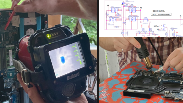
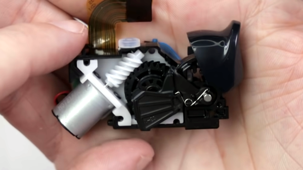
 The feedback for the trigger assembly is handled by a lever, a geared wheel, and a worm gear on an electric motor. Under normal circumstances, nothing interferes with the trigger at all and it works like a normal analog trigger. But when the motor moves the lever into place, trigger movement now has to overcome the added interference with a mechanical disadvantage. The amount of resistance felt can be increased a surprising amount by having the motor actively apply additional force to counter the trigger’s movement.


