A Smart Speaker That Reminds You It’s Listening

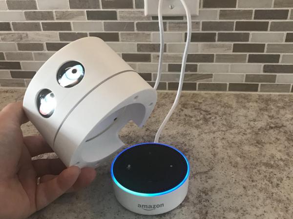
[markw2k9] has an Alexa device that sits in his kitchen and decided it was time to spruce it up with some rather uncanny eyes. With some inspiration from the Adafruit Uncanny Eyes project, which displays similar animated eyes, [markw2k9] designed a 3d printed shell that goes on top of a 2nd generation Amazon Echo. A teensy 3.2 powers two OLED displays and monitors the light ring to know when to turn the lights on and show that your smart speaker is listening. The eyes look around in a shifty sort of manner. Light from the echo’s LED ring is diffused through a piece of plexiglass that was lightly sanded on the outside ring and the eye lenses are 30mm cabochons (a glass lens often used for jewelry).

One hiccup is that the ring on the Echo will glow in a steady pattern when there’s a notification. As this would cause the OLEDs to be on almost continuously and concerned for the lifetime of the OLED panels, the decision was made to detect this condition in the state machine and go into a timeout state. With that issue solved, the whole thing came together nicely. Where this project really shines is the design and execution. The case is sleek PLA and the whole thing looks professional.

We’ve seen a few other projects inspired by the animated eyes project such as this Halloween themed robot that is honestly quite terrifying. The software and STL files for the smart speaker’s eyes are on Github and Thingiverse.

Continue reading “A Smart Speaker That Reminds You It’s Listening”

The Potatoes Of DOOM

Over the years, the 1993 classic Doom has gained an almost meme-like status where it can seemingly run on anything. Everything from printers to smartwatches has been shown off running the now-iconic first level of Doom. Looking to up the bar, [Equalo] set out to run Doom on potatoes. However until we develop full biological computers, he had to settle for running Doom on a device powered by potatoes. (Video, embedded below.)

As we’ve seen with other hacks before, potatoes are a decent power source that just requires potato, zinc, and copper. Some have attempted to make it easier to scale potato power and others have focused on making the individual potatoes more powerful. The biggest obstacle when working with potatoes as a battery is that even though each potato can put out almost a volt, the current is laughably small.

The lack of current is what drove [Equalo] to dramatically scale up the typical potato battery. With a target device of a Raspberry Pi Zero requiring around 100 mA at 4.5V, this means he needed over 700 potato slices. After boiling hundreds of potatoes and with a bit of help from friends and family, the giant potato battery was constructed, and we can’t help but marvel at the sheer scale and audacity. The challenge of scaling up a potato battery is that by the time you’re wiring up the 400th potato, your first potato has already started to corrode.

Next time you’re looking for some inspiration for a monumental task, perhaps watch the tale of [Equalo’s] giant potato battery and remember what can be accomplished with some determination and a hundred pounds of spuds.

Continue reading “The Potatoes Of DOOM”

A Breadboard Block For 8-Bit CPUs

Breadboard CPUs are a fantastic learning experience and require serious dedication and patience. Occasionally, CPU builders eschew their breadboards and fab their design onto a PCB. But this takes away the flexibility and some of the opportunity for learning that breadboard CPUs offer. [c0pperdragon] was doing the same sort of repetitive wiring from project to project as most 8-bit breadboard CPUs use memory, a bus, an IO controller, ROM, and a few other passive components.

Taking a compromise approach, [c0pperdragon] built a PCB that can be used as a building block in his custom CPUs which they have titled “ByteMachine”. A single row of 34 pins offer power, clock, reset, 19 address bus lines, 8 data bus lines, and a ROM selector. This means that the CPUs can fit on a single breadboard and can run faster as the impedance of the breadboard has less effect on the circuit. With 512 KB of RAM and 512 KB of ROM, in a ZIF socket for easy reprogramming, ByteMachine has plenty of space.

One drawback is the lack of IO. There is no dedicated address space as this would require decoding logic between the RAM and the CPU. [C0pperdragon] added a simple 8-bit output register provided by a 74-series logic IC. The data is displayed on 8 red LEDs and can be accessed via pins. Input is accomplished in a similar way with just 8 bits of digital input provided.

[C0pperdragon] has built the 65C02, 65C816Z84C00, and the i8088 with the ByteMachine. Each was documented with incredible schematics, pictures, and test programs on GitHub. Next time you’re looking to build a CPU on a breadboard, maybe start with a ByteMachine. In some ways, it might improve your learning experience as it makes the incredible mass of wires we’ve seen on other projects a tad more manageable.

Thanks [Reinhard Grafl] for sending this one in!

Spin The Video Track With A Mechanical Flair

One of the most difficult user interfaces to get right is video editing. It is complex and fiddly with large amounts of precision required even after four or five hours of straight editing. Seeking to bring some of that interface out into the real world, [Zack Freedman] built a mechanical video editing keyboard.

The keyboard in question features popular shortcuts and keys to breeze through different parts of editing. The biggest feature is, of course, the large scrubbing knob, allowing [Zack] to fly through long video with precision. We’ve seen our fair share of mechanical keyboards that aren’t traditional keyboards on Hackaday before, such as this number pad or this macro pad.

One of the unique constraints of this project was the fact that Zack had a deadline of two days. This self-imposed deadline was to help focus the work and drive it towards completion. This meant that it had to be designed in such a way that roadblocks or troublesome features could be designed around or cut out altogether. At its heart, this project is just 14 mechanical switches, 4 potentiometers, and a Teensy to drive it all. It is the design, prototyping, and thought that went into this project that makes it noteworthy. There are plenty of lessons here about how to manage a project’s timeline and advice about how to actually finish it.

Code, STL’s, diagrams, and instructions are all on his GitHub.

Continue reading “Spin The Video Track With A Mechanical Flair”

Throwing Down The FPGA Gauntlet

Gauntlet is a well-known arcade game from 1985 with many sequels and ports to more modern architectures such as Xbox and GameCube. Thanks to its popularity and relative age, the original arcade cabinet is well documented with the schematics available online. It was regarded as the most complex and ambitious hardware Atari had ever developed at the time it was released. In what can only be described as an absolute labor of love, [Alex] has recreated the arcade hardware on the Pipistrello FPGA board.

The project can actually play Gauntlet, Gauntlet II, and Vindicators II as they all ran on the same hardware. Four joysticks are supported so up to four players can play, though the EEPROM is emulated in RAM so high scores are reset when the device is powered down. The FPGA is almost out of space and can’t quite squeeze in the SRAM needed. So an SRAM expansion daughterboard is required; nothing a quick board run from our favorite purple PCB manufacturer can’t solve.

In the repo is an incredible write-up detailing the system, how it works, and the process of debugging it. This project also includes a complete simulation of the TMS5220 Voice Synthesis Processor, as Gauntlet was the first coin-operated arcade machine with a voice synthesizer. Getting the video correct was particularly tricky and it took several tries to get the color palette and motion looking right. Since [Alex] didn’t have access to an original Gauntlet arcade cabinet, they had to make do with MAME. After writing a test to make sure the FPGA was working correctly, there were differences between the MAME emulation and the FPGA output. To help out, [Colin Davies] came to the rescue. After [Colin] hooked up an original Gauntlet Arcade PCB with the motion test loaded up, the test showed that the FPGA had the correct behavior.

During development [Alex] actually simulated several frames of the game in ISIM (at a whopping 90 seconds per frame or 90 minutes per in-game second). Using ISIM allowed them to compare system state to MAME and validate the design much faster as they could better inspect the interworkings of the different modules. Using a clever trick of grabbing state from MAME after a few seconds, they primed the FPGA state and saved themselves a few hours of simulation.

If you’re looking to get into old hardware style arcade game development, give the browser-based 8bitworkshop IDE a spin. Or start with something a little smaller in scope and size with this adorable mini CRT arcade cabinet.

Continue reading “Throwing Down The FPGA Gauntlet”

Tube Amp Is Modeled With The Power Of AI

There is a certain magic and uniqueness to hardware, particularly when it comes to audio. Tube amplifiers are well-known and well-loved by audio enthusiasts and musicians alike. However, that uniqueness also comes with the price of the fact that gear takes up space and cannot be configured outside the bounds of what it was designed to do. [keyth72] has decided to take it upon themselves to recreate the smooth sound of the Fenders Blues Jr. small tube guitar amp. But rather than using hardware or standard audio software, the magic of AI was thrown at it.

In some ways, recreating a transformation is exactly what AI is designed for. There’s a clear and recordable input with a similar output. In this case, [keyth72] recorded several guitar sessions with the guitar audio sent through the device they wanted to recreate. Using WaveNet, they created a model that applies the transform to input audio in real-time. The Gain and EQ knobs were handled outside the model itself to keep things simple. Instructions on how to train your own model are included on the GitHub page.

While the model is simply approximating the real hardware, it still sounds quite impressive, and perhaps the next time you need a particular sound of your home-built amp or guitar pedal, you might reach for your computer instead.
Continue reading “Tube Amp Is Modeled With The Power Of AI”

Procedural Barcode Synth Is As Simple As Black And White

We are no stranger to peculiar and wonderful musical instruments here at Hackaday. [James Bruton] has long been fascinated with barcode scanners as an input source for music and now has a procedural barcode-powered synth to add to his growing collection of handmade instruments. We’ve previously covered his barcode guitar, which converts a string of numbers from the PS/2 output to pitches. This meant having a large number of barcodes printed as each pitch required a separate barcode. As you can imagine, this makes for a rather unwieldy and large instrument.

Rather than looking at the textual output of the reader, [James] cracked it open and put it to the oscilloscope. Once inside, he found a good source that outputs a square wave corresponding to the black and white lines that the barcode sees. Since the barcodes [James] is using don’t have the proper start and stop codes, the barcode reader continuously scans.  Normally it would stop the laser to send the text over the USB or PS/2 connection. A simple 5v to 3.3v level shifter feeds that square wave into a Teensy board, which outputs the audio.

A video showcasing a similar technique inspired [James] with this project. The creators of that video have a huge wall of different patterns of black and white lines. [James’s] next stroke of brilliance was to have a small HDMI display to generate the barcodes on the fly. A Raspberry Pi 4 reads in various buttons via GPIO and displays the resulting barcode on the screen. A quick 3d printed shell rounds out the build nicely, keeping things small and compact. All the code and CAD files are up on GitHub.

Continue reading “Procedural Barcode Synth Is As Simple As Black And White”