We’ve seen plenty of simple reflow ovens, and there’s an excellent chance that some of the people reading these words have even thrown their own together. A minimal example isn’t much more than a old toaster oven, a Solid State Relay (SSR), a thermocouple, and a microcontroller to get them all talking. But if you’re like [Mangy_Dog] and willing to put in a bit more effort, the final result can be a capable piece of equipment that will be the envy of the hackerspace.
 This build started as most do, with a search for a used toaster oven. But in the end he actually found a German model cheap enough that he could buy it new without going over budget for the project. Though he soon found out why: when it arrived, the so-called “pizza oven” was far smaller than he’d imagined. Luckily, it ended up being the perfect size for PCBs.
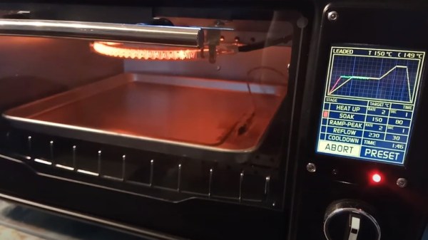
Unfortunately, the heating elements weren’t quite where he wanted them. Even after wrapping the heating chamber with ceramic insulation, a feature that was likely left off the original oven to cut costs, he says the temperature would only rise about 1 degree per second. So he added an additional halogen heating element at the top of the oven which pushed that rate up to 6 degrees per second.
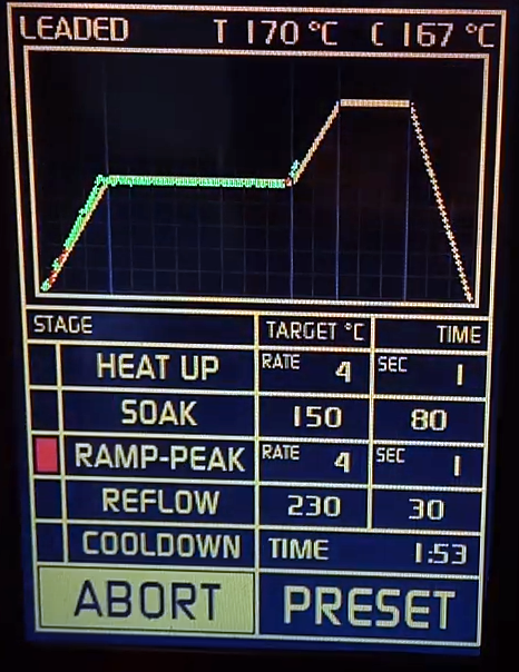
Control is provided by an Arduino Pro Mini and a touch screen display with some very slick graphics. There’s the expected thermocouple to detect the current temperature, but while the earlier versions of the electronics used the aforementioned SSR to control the heating elements, [Mangy_Dog] eventually replaced it with a dimmer module rated for 4000 watts. After coming up with a circuit that allowed him to control the dimmer with the Arduino, this module gave for much finer control over the chamber temperature. Plus it apparently kept all the lights in his house from flickering when the elements kicked in at 100%, which was a nice bonus.
This isn’t the first time we’ve seen somebody shoehorn an LCD into an off-the-shelf toaster oven, but it’s certainly one of the most polished examples to ever come our way. When even commercially available units need some hacking to reach feature parity with DIY versions, building your own reflow oven still seems like the way to go in 2020.
Continue reading “Touch Screen Reflow Oven Pulls Out All The Stops”