Keeping A 3D Printed NAS Updated With The Times

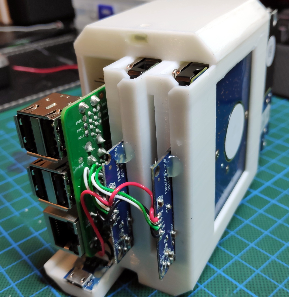
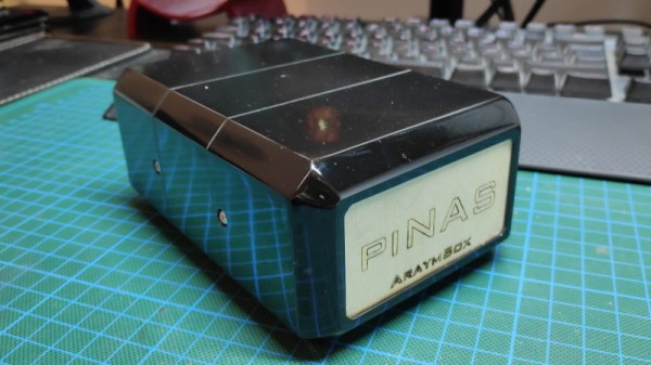
Back in 2018, [Paul-Louis Ageneau] created a 3D printed network-attached storage (NAS) enclosure for his Raspberry Pi. The design worked well, the Internet liked it when he posted the details on his blog, and all was right with the world. But of course, such glories are fleeting. Two years later that design needs updating, and thanks to the parametric nature of OpenSCAD, he’s been able to refresh his design for another tour of duty.

In our book, this is as much a cautionary tale as it is a success story. On one hand, it’s a testament to the power of CAD and desktop 3D printing. That a design can be tweaked and reproduced down the line with only minimal hassle is great for folks like us. But it’s also a shame that he didn’t get more than two years before some of the parts he used in the original NAS became unobtainium.

The main issue was that the integrated USB hub he used for the first version is no longer available, so the design had to be modified to accept a similar board. Unfortunately, the new hub is quite a bit wider than the old one. Resizing the entire case isn’t really an option since the Pi has to slide into it, so the hub now bumps out a bit on one side. He’s added a printable cover that cleans it up a bit, but the asymmetrical look might be a problem for some. While fiddling with the design, he also changed around the cooling setup so a larger fan could be mounted; now that the Raspberry Pi 4 is out, it can use all the cooling help it can get.

We covered the original version of the printed NAS back when it was first released, and it’s always good to see a creator coming back and keeping a project updated; even if it’s because hardware availability forced their hand.

A Custom Raspberry Pi 4 Arcade Cabinet

Over the years we’ve covered quite a few Raspberry Pi based arcade cabinets, and admittedly many of them have been fairly similar. After all, there’s only so much variation you can make before it stops looking like a traditional arcade machine. But even still, we never tire of seeing a well executed build like the one [Dawid Zittrich] recently shared with us.

These days you can order a kit that has pre-cut panels to build your cabinet with, but looking for a completely custom build, [Dawid] decided to first model his design in SketchUp and then cut out the panels himself with a jigsaw. This obviously is quite a bit more work, and assumes you’ve got sufficient woodworking tools, but we think the final result looks great. Not to mention the fact that it’s going to be a lot stronger than something made out of MDF.

He also created the side artwork himself, taking the logos and names from his favorite arcade and Amiga games and putting them on a retro-looking gradient pattern.  The marquee on the top has an acrylic front and is illuminated from behind with strips of LEDs. It’s mounted on a hinge so that it can be lifted up and a new piece of art slid in without taking apart the whole cabinet. While it might be a little more labor intensive to switch out than some of the electronic marquees we’ve seen, we do like that you still have the ability to change the artwork on a whim.

With the cabinet itself completed, [Dawid] turned his attention to the electronics. Inside you’ve got the aforementioned Raspberry Pi 4 (with a Noctua fan to keep it cool), an external hard drive, a HDMI to VGA converter with scanline generator to drive the 4:3 ratio Eizo Flex Scan S2100 monitor, and a rather beefy amplifier hanging off the Pi’s 3.5 mm analog audio output. All of which is easily accessible via a maintenance hatch built into the cabinet so [Dawid] doesn’t need to tear everything down when he wants to tweak something.

If you’d like to have that arcade cabinet feel but don’t have the space and equipment to put something like this together, you could always stick a Raspberry Pi into an iCade and call it a day.

Broken 3D Printer Turned Scanning Microscope

A few years ago, [Wayne] managed to blow out the main board of his Flashforge Finder attempting to change the fan. But the death of one tool ended up being the birth of another, as he ended up using its mechanical components and a Raspberry Pi to create an impressive scanning microscope.

Scan of Ulysses S. Grant from a US $50 bill

As you might have guessed from the name, the idea here is to scan across the object with a digital microscope to create an enlarged image of the entire thing. This requires some very precise control over the microscope, which just so happens to be exactly what 3D printers are good at. All [Wayne] had to do was remove the hotend, and print some adapter pieces which let him mount a USB microscope in its place.

The rest is in the software. The Raspberry Pi directs the stepper motors to move the camera across the object to be scanned in the X and Y dimensions, collecting thousands of individual images along the way. Since the focus of the microscope is fixed and there might be height variations in the object, the Z stage is then lifted up a few microns and the scan is done again. Once the software has collected tens of thousands of images in this manner, it sorts through them to find the ones that are in focus and stitch them all together.

The process is slow, and [Wayne] admits its not the most efficient approach to the problem. But judging by the sample images on the Hackaday.io page, we’d say it gets the job done. In fact, looking at these high resolution scans of 3D objects has us wondering if we might need a similar gadget here at the Hackaday Command Bunker.

The project is actually an evolution of an earlier attempt that used gutted optical drives to move the microscope around.

Lessons Learned From A CubeSat Postmortem

On the 3rd of June 2019, a 1U CubeSat developed by students of the AGH University of Science and Technology in Kraków was released from the International Space Station. Within a few hours it was clear something was wrong, and by July 30th, the satellite was barely functional. A number of problems contributed to the gradual degradation of the KRAKsat spacecraft, which the team has thoroughly documented in a recently released paper.

We all know, at least in a general sense, that building and operating a spacecraft is an exceptionally difficult task on a technical level. But reading through the 20-pages of “KRAKsat Lessons Learned” gives you practical examples of just how many things can go wrong.

KRAKsat being released from the ISS

It all started with a steadily decreasing battery voltage. The voltage was dropping slowly enough that the team knew the solar panels were doing something, but unfortunately the KRAKsat didn’t have a way of reporting their output. This made it difficult to diagnose the energy deficit, but the team believes the issue may have been that the tumbling of the spacecraft meant the panels weren’t exposed to the amount of direct sunlight they had anticipated.

This slow energy drain continued until the voltage dropped to the point that the power supply shut down, and that’s were things really started going south. Once the satellite shut down the batteries were able to start charging back up, which normally would have been a good thing. But unfortunately the KRAKsat had no mechanism to remain powered down once the voltage climbed back above the shutoff threshold. This caused the satellite to enter into and loop where it would reboot itself as many as 150 times per orbit (approximately 90 minutes).

The paper then goes into a laundry list of other problems that contributed to KRAKsat’s failure. For example, the satellite had redundant radios onboard, but the software on them wasn’t identical. When they needed to switch over to the secondary radio, they found that a glitch in its software meant it was unable to access some portions of the onboard flash storage. The team also identified the lack of a filesystem on the flash storage as another stumbling block; having to pull things out using a pointer and the specific memory address was a cumbersome and time consuming task made all the more difficult by the spacecraft’s deteriorating condition.

Of course, building a satellite that was able to operate for a couple weeks is still an impressive achievement for a student team. As we’ve seen recently, even the pros can run into some serious technical issues once the spacecraft leaves the lab and is operating on its own.

[Thanks to ppkt for the tip.]

A Raspberry Pi Terminal That’s Always Within Reach

Inspired by films such as The Matrix, where hackers are surrounded by displays and keyboards on articulated arms, [Jay Doscher] created this cyberpunk “floating” terminal so your favorite Linux single board computer is always close at hand. Do you actually need such a thing mounted to the wall next to the workbench? Probably not. But when has that ever stopped a Hackaday reader?

[Jay] has come up with a modular design for the “A.R.M. Terminal” that allows the user to easily augment it with additional hardware. The 3D printed frame of the terminal has hardpoints to bolt on new modules, which thanks to threaded metal inserts, will have no problem surviving multiple configurations.

This initial version features a panel on the left side that holds various buttons and switches attached to the Pi’s GPIO pins. With a bit of code, it’s easy to pick up the status of these controls and use them to fire off whatever tasks your imagination can come up with. On the bottom [Jay] has mounted a stand-alone VFD audio spectrum display that’s hooked up to the Pi’s 3.5 mm jack. It’s totally unnecessary and costs as much as the Raspberry Pi itself, but it sure is pretty.

If there’s a downside to the design, it’s that the only display currently supported is the official Raspberry Pi touchscreen which is only 800×480 and a bit pricey compared to more modern panels. On the other hand, there’s something to be said for the standardized bolt pattern on the back of the official screen; so if you want to use a higher resolution display, be prepared to design your own mounting bracket. Extra points if you share your changes with the rest of the class.

For anyone who likes the look of the A.R.M. Terminal but isn’t too keen on being tethered to the wall, you’re in luck. [Jay] previously created the Raspberry Pi Recovery Kit which shares many of the same design principles but puts them into a ruggedized case that’s ready for life in the field.

A Battery Sipping Cellular Mailbox Notifier

Like many of us, [Zak Kemble] has an indeterminate number of tiny packages coming his way from all over the globe at any given time. Unfortunately, the somewhat unpredictable nature of the postal service where he lives meant he found himself making a lot of wasted trips out to the mailbox to see if any overseas treasures had arrived for him. To solve the problem, he decided to build an Internet-connected mailbox notification system that could work within some fairly specific parameters.

For one thing, the mailbox is too distant to connect directly to it over WiFi. [Zak] mentions that 433 MHz might have been an option, but he decided to skip that entirely and just connect it to the cellular network with an A9G GPRS/GSM module from A.I. Thinker. This device actually has its own SDK that allows you to create a custom firmware for it, but unfortunately the high energy consumption of the radio meant it would chew through batteries too quickly unless it had a little extra help.

Not wanting to have to change the batteries every couple months, [Zak] added a ATtiny402 to handle the notifier’s power management needs. By using a P-MOSFET to completely cut power to the A9G, the notifier can save an incredible amount of energy by only activating the cellular connection once it actually needs to send a notification; which in this case takes the form of an HTTP request that eventually works its way to a Telegram group chat.

To cut a long story short, testing seems to indicate that the notifier can fire off approximately 800 requests before needing its 10440 lithium battery recharged. Given how often [Zak] usually receives mail, he says that should last him around five years.

The A9G module, the ATtiny402, a BME280 environmental sensor (because, why not?), the battery, and all the ancillary support hardware are on a very professional looking PCB. That goes into a relatively rugged enclosure that’s designed to keep the electronics from shorting out on the mailbox’s metal case as well as keeping any particularly weighty parcels from crushing it.

If you’ve got the freedom so mount whatever you want outside, then you can certainly build a more technically impressive mailbox. But considering the limitations [Zak] had to work around, we think he did an excellent job.

A Retro Touch Pad You Can Use On Modern Computers

As [Jan Derogee] explains in the faux-retro video after the break, drawing on classic 8-bit computers was something of a pain. The rudimentary light pens and joysticks of the 1980s allowed for free-form input, but were clumsy and awkward to use. Which is why he set out to create an ideal drawing device for the C64 using modern electronics. For the sake of completion, he also gave it a USB HID mode so it would work on somewhat more modern computers.

His device, which he’s calling the Commo Pad, looks like it could have been transported here directly from the 1980s, but it’s built from entirely new hardware. The case is actually made of wood that [Jan] sanded and painted to give it that chunky plastic aesthetic that we all know and love, and the retro artwork on the touch panel really goes a long way to sell the vintage vibe.

Speaking of which, the touch panel is perhaps the most interesting component of the entire build. It’s actually a resistive panel that was meant for mounting to an LCD that [Jan] has connected to an Arduino. All he had to do was provide a stable frame for it and print out some art work to slide in behind it.

The Arduino and associated electronics allow the Commo Pad to be picked up by the C64 as either a joystick or mouse, which means it doesn’t need any custom software on the computer side to function. Similarly, it can also mimic a USB mouse if you want to plug it into something made a bit later than 1982. Should you be so inclined to make it wireless, the addition of a Bluetooth seems like it would be relatively trivial.

If the Commo Pad doesn’t have enough of a retro-futuristic vibe for your tastes, we recently covered a custom optical touch panel that looked like it could double as a prop from Blade Runner which might do the trick.

Continue reading “A Retro Touch Pad You Can Use On Modern Computers”