Cheap Front Panels With Dibond Aluminium

The production capability available to the individual hacker today is really quite incredible. Even a low-end laser engraver can etch your PCBs, and it doesn’t take a top of the line 3D printer to knock out a nice looking enclosure. With the wide availability of these (relatively) cheap machines, the home builder can churn out a very impressive one-off device on a fairly meager budget. Even low volume production isn’t entirely out of the question. But there’s still one element to a professional looking device that remains frustratingly difficult: a good looking front panel.

Now if your laser is strong enough to engrave (and ideally cut) aluminum sheets, then you’ve largely solved this problem. But for those of us who are plodding along with a cheap imported diode laser, getting text and images onto a piece of metal can be rather tricky. On Hackaday.io, [oaox] has demonstrated a cost effective way to create metal front panels for your devices using a print service that offers Dibond aluminum. Consisting of two thin layers of aluminum with a solid polyethylene core, this composite material was designed specifically for signage. Through various online services, you can have whatever you wish printed on a sheet of pre-cut Dibond without spending a lot of money.

As explained by [oaox], the first step is putting together the image you’ll send off to the printer using a software package like Inkscape. The key is to properly define the size of the Dibond plate in your software and work within those confines, otherwise the layout might not look how you expected once the finish piece gets back to you. It’s also important to avoid lossy compression formats like JPEG when sending the file out for production, as it can turn text into a mushy mess.

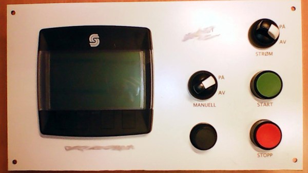
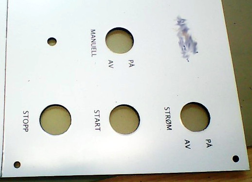
When you get the sheet back, all you need to do is put your holes in it. Thanks to the plastic core, Dibond is fairly easy to cut and drill as long as you take your time. [oaox] used a step drill for the holes, and a small coping saw for the larger openings. The final result looks great, and required very little effort in the grand scheme of things.

But how much does it cost? Looking around online, we were quoted prices as low as $7 USD to do a full-color 4×4 inch Dibond panel, and one site offered a 12×12 panel for $20. For a small production run, you could fit several copies of the graphics onto one larger panel and cut them out with a bandsaw; that could drop the per-unit price to only a couple bucks.

We’ve seen some clever attempts at professional looking front panels, from inkjet printing on transparencies to taking the nuclear option and laser cutting thin plywood. This is one of those issues the community has been struggling with for years, but at least it looks like we’re finally getting some decent options.

A Crash Course In Reliable Communication

It’s probably fair to say that anyone reading these words understands conceptually how physically connected devices communicate with each other. In the most basic configuration, one wire establishes a common ground as a shared reference point and then the “signal” is sent over a second wire. But what actually is a signal, how do the devices stay synchronized, and what happens when a dodgy link causes some data to go missing?

All of these questions, and more, are addressed by [Ben Eater] in his fascinating series on data transmission. He takes a very low-level approach to explaining the basics of communication, starting with the concept of non-return-to-zero encoding and working his way to a shared clock signal to make sure all of the devices in the network are in step. Most of us are familiar with the data and clock wires used in serial communications protocols like I2C, but rarely do you get to see such a clear and detailed explanation of how it all works.

He demonstrates the challenge of getting two independent devices to communicate, trying in vain to adjust the delays on the receiving and transmitting Arduinos to try to establish a reliable link at a leisurely five bits per second. But even at this digital snail’s pace, errors pop up within a few seconds. [Ben] goes on to show that the oscillators used in consumer electronics simply aren’t consistent enough between devices to stay synchronized for more than a few hundred bits. Until atomic clocks come standard on the Arduino, it’s just not an option.

[Ben] then explains the concept of a dedicated clock signal, and how it can be used to make sure the devices are in sync even if their local clocks drift around. As he shows, as long as the data signal and the clock signal are hitting at the same time, the actual timing doesn’t matter much. Even within the confines of this basic demo, some drift in the clock signal is observed, but it has no detrimental effect on communication.

In the next part of the series, [Ben] will tackle error correction techniques. Until then, you might want to check out the fantastic piece [Elliot Williams] put together on I2C.

[Thanks to George Graves for the tip.]

Continue reading “A Crash Course In Reliable Communication”

Poetry Is The Fruit Of This Loom

We’d wager that most people reading these words have never used a loom before. Nor have most of you churned butter, or ridden in a horse-drawn wagon. Despite these things being state of the art technology at one point, today the average person is only dimly aware of their existence. In the developed world, life has moved on. We don’t make our own clothes or grow our own crops. We consume, but the where and how of production has become nebulous to us.

[David Heisserer] and his wife [Danielle Everine], believe this modern separation between consumption and production is a mistake. How can we appreciate where our clothing comes from, much less the people who make it, without understanding the domestic labor that was once required to produce even a simple garment? In an effort to educate the public on textile production in a fun and meaningful way, they’ve created a poetry printing loom called Meme Weaver.

The Meme Weaver will be cranking out words of woolen wisdom at the Northern Spark Festival taking place June 15th and 16th in downtown Minneapolis. If any Hackaday readers in the area get a chance to check out the machine, we’d love to hear about it in the comments. Take photos! Just don’t blame us if you have a sudden urge to make all of your clothing afterwards.
Continue reading “Poetry Is The Fruit Of This Loom”

VCF East 2018: Cactus, Retro Because It Wants To Be

Among the rows of digital dinosaurs, one blinking front panel stood out. It certainly looked the part of a retro computer; with banks of blinking LEDs and multicolored paddle switches. But upon closer inspection, the laser cut wooden front panel betrays the fact that this machine is an impostor. It may have the appearance of a machine from the heady days where home computers looked like they could have doubled as a prop on the bridge of Kirk’s Enterprise, but it’s actually a product of much more modern provenance.

It’s called the Cactus, a love letter to the homebrew microcomputers of the 1970’s, designed and built by somebody at least 20 years too young to have experienced them the first time around. Alexander Pierson created the Cactus not because he had fond memories of putting together an Altair 8800 in 1975, but because he’s fascinated with the retro computer experience: the look of the front panel, the satisfying clunk of era-appropriate switches, and the idea that the computer’s inner workings aren’t an abstract black box but rather something you can interact with and study. Judging by all the attention the Cactus got at VCF East XIII, he’s not the only one.

Let’s take a look at everything Alexander poured into this retrocomputer build.

Continue reading “VCF East 2018: Cactus, Retro Because It Wants To Be”

Unlocking Animal Crossing’s Debug Mode

Originally released on the Nintendo 64 in 2001, Animal Crossing was the first entry into what has become a massively successful franchise. But while the game has appeared on more modern Nintendo consoles, most recently Android and iOS, the version released on the GameCube holds a special place in many fan’s hearts. The GameCube version was the first time those outside of Japan got a taste of the unique community simulation offered by Animal Crossing, and maintains a following nearly 20 years after its release.

[James Chambers] has recently been investigating creating mods for the GameCube version of Animal Crossing, and in the process uncovered some interesting references to a debug mode. That launched a deep dive into the game’s assembly code in an attempt to find what the debug functions did and if they could be enabled without having to patch the game ROM. In the end, he was able to find a push button code that enables debug mode on the retail copy of the game.

[James] starts by using the debugger provided by the Dolphin GameCube emulator to poke around and figure out exactly what flags need to be modified to activate the debug mode. This leads to a few interesting finds, such as being able to pop up a performance monitor graph and some build info. Eventually he finds the proper incantation to bring up a functional debug display in the game, but there was still the mystery of how you do it on the real hardware with a retail copy of the game.

It wouldn’t be unreasonable to think that some special dongle or development version of the GameCube would be required to kick the game into debug mode. But through careful examination of the code path, [James] was able to figure out that hitting a specific combination of buttons on the controller was all that was required to use the debug mode on the stock game. Once the debug mode is started, a controller plugged into the second port allows the user to navigate through options and perform tasks. Not everything is currently understood, but some progress has been made, such as figuring out how to add items to your inventory.

It’s hardly Nintendo’s most popular console, but there’s still a healthy interest in GameCube hacking as the machine approaches its 20th anniversary. We recently saw some impressive work being done to reverse engineer the system’s wireless controllers, though some people are more interested in just cutting the thing in half.

[Thanks to Tim Trzepacz for the tip.]

Chromebook Trades Camera For WiFi Freedom

There are a number of companies now providing turn-key computers that meet the Free Software Foundation’s criteria for their “Respects Your Freedom” certification. This means, in a general sense, that the computer is guaranteed not to spy on you or otherwise do anything else you didn’t explicitly ask it to. Unfortunately these machines often have a hefty premium tacked on, making it an unpleasant decision between privacy and performance.

Freedom-loving hacker [SolidHal] writes in to tell us about his quest to create a FSF-compliant laptop without breaking the bank. Based on a cheap Asus C201 Chromebook, his custom machine checks off all the appropriate boxes. The operating system was easy enough with an install of Debian, and the bootloader was rid of any Intel Management Engine shenanigans with a healthy dose of Libreboot. But there was one problem: the permanently installed WiFi hardware that required proprietary firmware. To remedy the issue, he decided to install an internal USB Wi-Fi adapter that has the FSF seal of approval.

As the Chromebook obviously doesn’t have an internal USB port, this was easier said than done. But as [SolidHal] is not the kind of guy who would want his laptop taking pictures of him in the first place, he had the idea to take the internal USB connection used by the integrated webcam and use that. He pulled the webcam out, studied the wiring, and determined which wires corresponded to the normal USB pinout.

The FSF approved ThinkPenguin Wi-Fi adapter he chose is exceptionally small, so it was easy enough to tuck it inside some empty space inside of the Chromebook. [SolidHal] just needed to solder it to the old webcam connection, and wrap it up in Kapton tape to prevent any possible shorts. The signal probably isn’t great considering the antenna is stuck inside the machine with all the noisy components, but it’s a trade-off for having a fully free and open source driver. But as already established, sometimes these are the kind of tough choices you have to make when walking in the righteous footsteps of Saint Ignucius.

Internal laptop modifications like this one remind us of the Ye Olden Days of Hackaday, when Eee PC modifications were all the rage and we still ran black and white pictures “taped” to the screen. Ah, the memories.

Framed Raspberry Pi Keeps Tabs On Spotify

Perhaps you’ve noticed, but we here at Hackaday have a slight obsession with the over-engineered. One could fairly say there’s a linear relationship between how likely we are to feature a project and how needlessly complex it is. That said, it isn’t as if we are unable to appreciate a minimalist approach. Taking the scenic route can be a lot of fun, but sometimes it’s nice to just get where you’re going before you run out of gas.

This very slick Spotify “Now Playing” display created by [Jon Ashcroft] is a perfect example of that principle. The hardware is so straightforward that it’s barely worth mentioning: a Raspberry Pi with a small HDMI display, tucked neatly into a photo frame. Nothing to get too excited about there. The real hook with this particular project is the software.

[Jon] is a web developer by trade, so it’s natural he would approach his personal projects with that same mentality. Rather than one of the “usual suspects” for a Pi project like Python, he wrote his software in ES6; which the Pi is running through Chromium in kiosk mode (full screen web content, no top bar). For those of you who aren’t keeping up on web languages, ES6 is short for EcmaScript 6: a new version of the standard on which JavaScript is based. It’s a bit heavier on resources than is strictly necessary, but it works well enough in the end.

Using Spotify’s excellent API, his software pulls down the current track information and stores it locally. It does this every ~4 seconds, checking to see if the track has changed. [Jon] isn’t thrilled with this brute force method, but it works for now. It displays the current playing song and artist, and uses a library called node-vibrant to extract a dominant color from the album art and use that to create a complementary background color. Very slick.

[Jon] provides all of his source code and made it easy to connect to your own Spotify account, so don’t be surprised if you see this running on a “Magic Mirror” near you soon.