While electromyography (EMG) is great for identifying neuro-muscular abnormalities and allows for amazing prosthetic limbs to work, it can also be used for fun. As you’ll see in the video after the break, accurate block-stacking (and possible candy-grabbing) depends on teamwork and tensed muscles.
Though the user provides the muscle, the brains behind this operation is an Arduino Uno with a Muscle BioAmp shield stacked on top, which [Upside Down Labs] also created. This shield makes it ridiculously easy to connect EMG sensors and other I²C devices like screens and, well, servo claws. From there, it’s really just a matter of printing the claw, connecting it to a 9g servo, and using an accompanying kit to prepare the skin and connect the muscles to the Arduino. Be sure to check it out in tense block-stacking action after the break.
If you want to listen in on your muscles, look no further than the BioAmp EMG Pill.
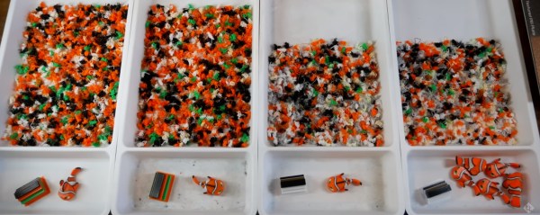
While multicolor printing eliminates painting steps and produces vibrant objects, there are two significant downsides; filament consumption and print time. A single-nozzle filament printer needs to switch from one color to another, and doing so involves switching to the other filament and then purging the transition filament that contains a mixture of both colors, before resuming the print with the clean new color.
[teachingtech] tests out a variety of methods for reducing print time and waste. One surprising result was that purging into the infill didn’t result in significant savings, even when the infill was as high as 50%. Things that did have a positive effect included reducing the amount of purge per transition based on light to dark color changes, and printing multiple copies at once so that even though the total amount of waste was the same as a single part, the waste per part was reduced.
All of the tests were with the same model, which had 229 color changes within a small part, so your mileage may vary, but it’s an interesting investigation into some of the deeper settings within the slicer. Reducing filament waste and print time is an admirable goal, and if you make your own extruder, you can turn all of that purge waste into various shades of greenish brownish filament. Continue reading “Reducing Poop On Multicolor Prints”→
The song was written by lead vocalist [Brian Mazzaferri] with inspiration from the classic Dr. Seuss book. [Brian] wrote it for his newborn daughter, and we’re pretty sure it will hit any parent right in the feels.
[Mootroidxproductions] isn’t a parent themselves, but they expanded on the theme to create a video about sacrificing oneself to save a loved one. With a self deprecating wit, they take us through the process of turning broken Bionicle parts, bits of Gundam, Lego, and, armature wire to make the two robots in the film. He also explains how he converted garbage into sets, greebles, and lighting effects.
The robots had to be designed so that they could fulfill their roles in the film. From the size of their hands down to their individual walking gaits, he thought of everything. His encyclopedic knowledge of Bionicle parts is also on full display as he explains the origin of the major parts used to build “Little Blue” and “Sherman”
Click through the break for both the main video and the behind-the-scenes production.
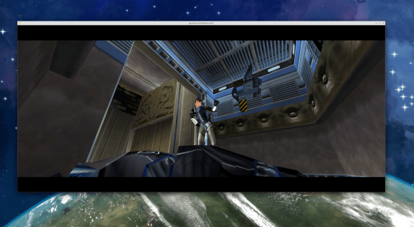
There’s an interesting renaissance of Nintendo 64 gaming, powered by the ability to decompile N64 ROMs back into C code using Ghidra. There are projects around multiple classic games, taking the Ghidra output and renaming the generic function and variable names. There are two approaches to these projects, sometimes happening in parallel. The first is to perfectly recreate the original work, and get a bit-perfect binary that matches the original ROM. The other approach is to fix bugs, optimize the code, and add new features, often porting to new platforms in the process. Right now, we’re seeing the latter happen with 2000’s Perfect Dark.
The game now runs on Windows or Linux, has mouse support, and runs at a solid 60 frames per second (FPS) at multiple screen resolutions. Want an ultra-widescreen Perfect Dark experience? The upgraded rendering engine handles it wonderfully. Mods? No problem. In the future, the developer is also looking to support high-definition textures.
To play, you do have to provide your own legally sourced copy of the original Perfect Dark game. That is the only way this project is remotely legal, and we suspect that even then it’s in a somewhat grey zone, as a derivative work of a copyrighted game. Big N hasn’t shut the project down, but the Mario 64 port was killed for attempting the same thing. We’ll hope for the best, and enjoy the nostalgia trip in the meanwhile!
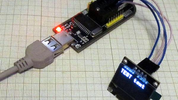
A handy tool to have on the bench is a Flash chip programmer, and the ones based around the CH341A USB bus converter chip are readily available. But the chip is capable of so much more than simply programming nonvolatile memory, so [Tomasz Ostrowski] has created a utility program that expands its capabilities. The software provides easy access to a range of common i2c peripherals. He’s got it talking to smart batteries, GPIOs, environmental sensors, an OLED display, and even an FM radio module. The code can all be found in a GitHub repository. The software is Windows-only so no fun and games for Linux users yet — but since it’s open source, new features are just a pull request away.
The CH341A is much more than an i2C controller, it also supports a surprising range of other interfaces including SPI, UARTs, and even a bidirectional parallel printer port. Maybe this software will serve to fire the imagination of a few others, and who knows, we could see more extended use of this versatile chip. Oddly we’ve featured these programmer boards before, though in a tricky flashing job.
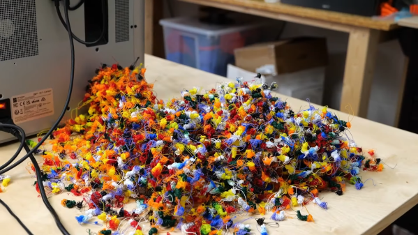
The fundamental problem with multi-color 3D printing using a single hotend is that they poop an awful lot. Every time they change filaments, they’ve got to purge the single nozzle, which results in a huge number of technicolor “purge poops” which on some machines are even ejected out a chute at the back of the printer. The jokes practically write themselves.
What’s not a joke, though, is the sheer mass of plastic waste this can produce. [Stefan] from CNC Kitchen managed to generate over a kilo of printer poop for a 500-gram multi-color print. So he set about looking for ways to turn printer poops back into filament, with interesting results. The tests are based around a commercial lab-scale filament extruder, a 3Devo Composer, but should apply to almost any filament extruder, even the homebrew ones. A few process tips quickly became evident. First, purge poops are too big and stringy (ick) to feed directly into a filament extruder, so shredding was necessary.
Second, everything needs to be very clean — no cross-contamination with plastics other than PLA, no metal bits in the chopped-up plastic bits, and most importantly, no water contamination. [Stefan]’s first batch of recycled filament came from purge poops that had been sitting around a while, and sucked a lot of water vapor from the air. A treatment in a heated vacuum chamber seems to help, but what worked best was using purge poops hot and fresh from a print run. Again, ick.
[Stefan] eventually got a process down that produced decent, usable filament that would jam the printer or result in poor print quality. It even had a pretty nice color, which of course is totally dependent on the mix of colors you start with. Granted, not everyone has access to a fancy filament extruder like his, so this may not be practical for everyone, but it at least shows that there’s a path to reducing the waste stream from any printer, especially multi-material ones.
As one of the most famous Ancient Egyptian pyramids, the Pyramid of Khafre on the plateau of Giza has been a true wonder of the Ancient World ever since its construction around 2570 BCE. Today, well over 4,500 years later, we are still as puzzled as our ancestors over the past hundreds of years how exactly this and other pyramids were constructed. Although many theories exist, including ramps that envelop the entire pyramid, to intricate construction methods from the inside out, the only evidence we have left are these pyramids themselves.
This is where the jokingly called [History for Granite] channel on YouTube has now pitched some new ideas, involving the casing stones that used to fully cover the Pyramid of Khafre, prior to widespread theft and vandalism.
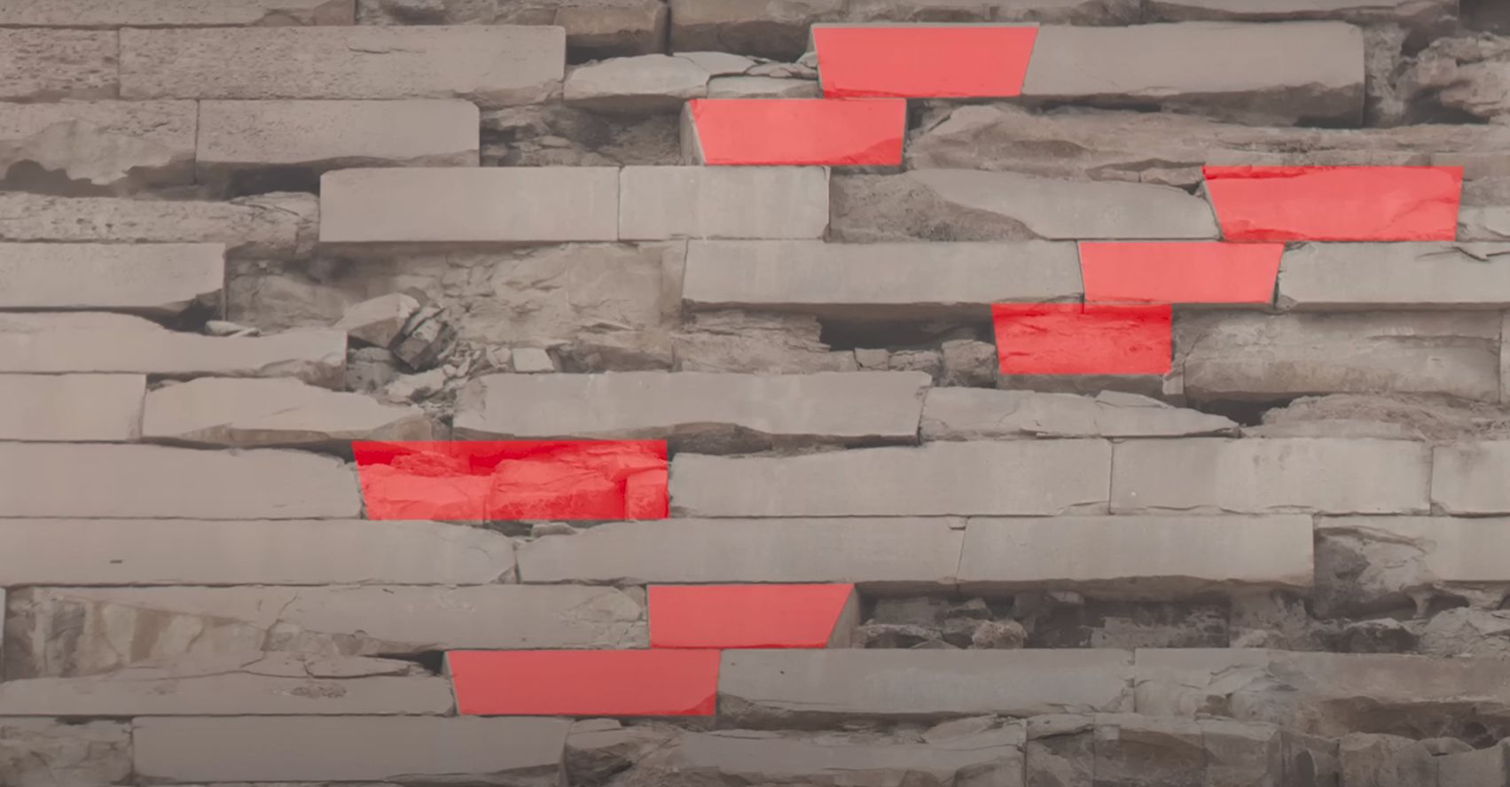
Bonding stones within the casing stones on the Pyramid of Khafre. (Credit: History for Granite, YouTube)
Despite the pyramids of Giza in particular being a veritable tourist trap, said tourists are heavily discouraged from climbing onto the pyramids, or even set up high-powered camera gear on tripods near them. Even with drone footage available, it was necessary to get a zoomed-in look on the casing stones that remain on the pyramid of Khafre near its top at well over 100 meters. Working within these limitations, it was possible to take detailed photos of three sides of the pyramid, which revealed interesting details.
In the top screenshot from the video the top of the pyramid is visible, which gives some indication of just how much the pyramid may have shifted out of alignment due to earthquakes over the millennia. This turned out to be not significant enough to account for some purported ‘gaps’ between the casing stones, with supposed ‘filler material’ from scaffolding holes explainable as just broken off sections of these casing stones. What was more interesting was that a pattern could be found in so-called bonding stones.
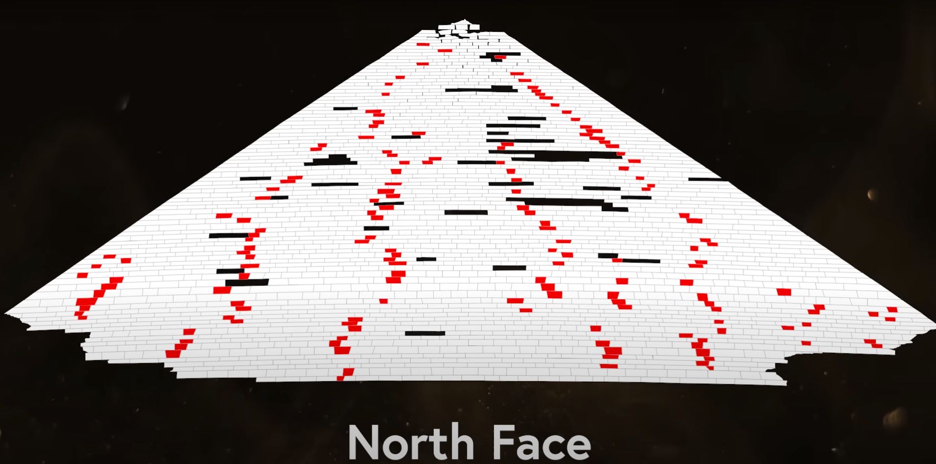
Pattern of bonding stones on the north face of the pyramid of Khafre. (Credit: History for Granite, YouTube)
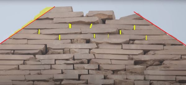
These bonding stones have a slanted end, so that they can be lifted slightly above a matching slanted stone, before being lowered to complete a row of bricks or stonework. After analyzing the three faces of the still mostly intact casing stones, a clear pattern emerged, such as that on the north face, pictured here.
What this suggests is that each row of casing stones were laid down by multiple groups of workers, each starting at a specific point before coming together where those sections would be joined with a bonding stone. This lends credence to the theory that the pyramid was constructed layer by layer, including the outer covering. To further examine these clues, the even older Bent Pyramid at the royal necropolis of Dahshur with mostly intact casing stones will be examined in more detail next.
If anything this series shows just how much there still is that we don’t know about these massive construction projects that are really only preceded by the works of the Sumerian and Akkadian people.