If you’ve ever thought that your floor cleaning robot eating the fringe on your rug wasn’t destructive enough, [Kyle Brinkerhoff] is working on a solution — Doomba.
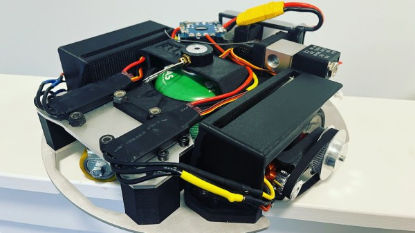
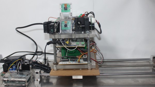
This blazingly fast RC vehicle has a tank of butane/propane gas nestled snugly amid its electronics and drive system to fuel a (not yet implemented) flamethrower. Watching how quickly this little bot can move in the video below certainly made our hearts race with anticipation for the inevitable fireworks glory of completed build. Dual motors and a tank-style drive ensure that this firebug will be able to maneuver around any obstacle.
As of writing, the flamethrower and an updated carriage for the drivetrain are underway. Apparently, spinning very quickly in circles can be just as disorienting for robots as it is for us biological beings. During the test shown below, the robot kicked out one of its drive motors. [Kyle] says the final touch will be putting the whole assembly inside an actual Roomba shell for that authentic look.
With spooky season upon us, it’s always good to have the cleansing power of fire at hand in case you find more than you bargained for with your Ghost-Hunting PKE Meter. While there’s no indication whether Doomba can actually run DOOM, you might be interested in this other Doomba Project that uses Roomba’s maps of your house to generate levels for the iconic shooter.
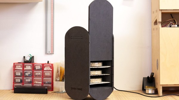
 This fermenter’s controller drives a heating element, which adheres to a pre-programmed fermentation cycle. It also has a fan for airflow and keeping the heat uniform.


