Among the plethora of obsolete removable media there are some which are lamented, but it can be difficult to find those who regret the passing of the floppy disk. These flexible magnetic disks in hard plastic covers were a staple of computing until some time in the early 2000s, and their drives could be found by the crateload in any spares box. But what about today, when there’s a need for a real floppy drive and none is to be found? Enter [Acemi Elektronikci], with an Arduino Nano based floppy emulator, that plugs into the floppy port of a PC old enough to have one, and allows the easy use of virtual floppy disks.
Aside from the Nano it has an SD card and associated level shifter, and an SSD1306 i2c screen. Most of the Arduino’s lines drive the floppy interface, so the five-button control comes to a single ADC pin via a resistor ladder. He freely admits that it’s not a perfect cycle-exact emulator of original hardware and there may be machines or even operating systems that complain when faced with it, but for all that it is a useful tool. One of the machines that may have issues is the Amiga, but fortunately there’s a fix for that with a Raspberry Pi.
We found a couple of headlines this week that seemed pretty alarming at first, mentioning as they did both “Chinese grannies” and “stun guns.” Digging a little deeper, it appears that widespread elder abuse isn’t what this is about, although there certainly is an unsavory aspect to the story. Apparently, it’s pretty common in Chinese cities for large groups of people to get together for exercise, with “square dancing” being one popular form. This isn’t the “do-si-do and allemande right” square dancing that made high school gym class really awkward for a few days, but rather large groups of mostly older women busting moves to Chinese music in public spaces. It’s the music that’s bothering some people, enough so that they’re buying “stun guns” that can somehow turn off the dancing grannies’ music. None of the articles go into any detail on the device besides describing it as a flashlight-looking thing, and that it appears to do no permanent damage to the sound system. We’d love to know where to get one of these things — you know, for science. And really, it’s kind of sad that people are taking offense at senior citizens just looking for a bit of exercise and social contact.
A couple of weeks back, we mentioned TeachMePCB, a free online PCB design class designed to take you from zero to PCB designer. We’ve been working through the course material and enjoying it, but it strikes us that there’s a lot to keep track when you’re designing a PCB, especially if you’re new to the game. That’s where this very detailed PCB design checklist would come in handy. It takes you right from schematic review and breadboard testing of subassemblies right through to routing traces to avoid crosstalk and stray capacitance problems, and right on to panelization tips and even how to make sure assembly services get your build right. Reading through the list, you get the feeling that each item is something that tripped up the author (grosdode) at one time or another. So it’s a little like having someone with hard-won experience watching over your shoulder as you work, and that can’t really be a bad thing.
Our friend Jeroen Vleggaar over at Huygens Optics on YouTube posted a video the other day about building an entire Schmidt-Cassegrain reflecting telescope out of a single piece of glass. The video is mostly an interview with optical engineer Rik ter Horst, who took up the building of monolithic telescopes as a hobby. It turns out that one of his scopes will be flying to space aboard a cubesat in January. If you’re a fan of precision optics, you’ll want to check this out. Jeroen also teased that he’ll be building his own version of Rik’s monolithic telescope, so watch for an article on that soon.
Heads up — applications are now being accepted for the Open Hardware Summit’s Ada Lovelace Fellowships. This year there are up to ten fellowships offered, each of which includes a $500 travel stipend to attend the Open Hardware Summit in April. The fellowships seek to foster a more diverse community in open-source hardware; applications are being accepted until December 17th, so hurry.
And finally, if you’ve got some spare cycles, you might want to turn your Mark 1 eyeballs to the task of spotting walrus from space. The World Wildlife Federation (WWF) is crowdsourcing its walrus census efforts by training people to spot the well-armed marine mammals in satellite photos. Assessing population numbers and distribution is important to understanding their ecology, and walrus are cute and cuddly (no, they’re not), so getting people to count them makes sense. But this seems like a job for machine vision — there has to be a model trained to recognize walrus, right? Or maybe just something to count dark spots against a white background? Maybe someone can whip something up to make this job a bit easier and less subjective.
Despite the name, BASIC isn’t exactly a language recommended for beginners these days. Technology has moved on, and now most people would steer you towards Python if you wanted to get your feet wet with software development. But for those who got their first taste of programming by copying lines of BASIC out of a computer magazine, the language still holds a certain nostalgic appeal.
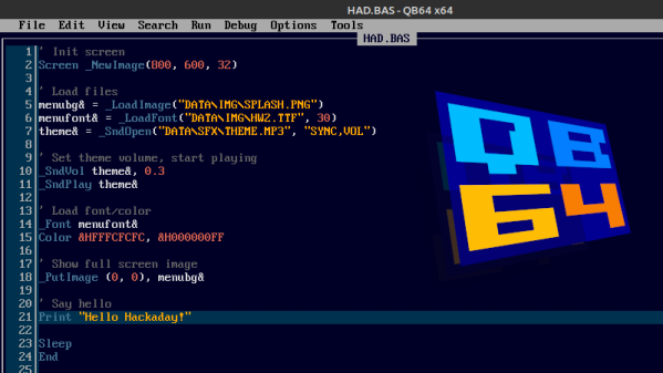
If that sounds like you, then may we heartily recommend QB64. The open source project seeks to modernize the classic programming language while retaining compatibility for QBasic 4.5, the late-80s BASIC environment Microsoft included with MS-DOS. That modernization not only includes the addition of contemporary technology like OpenGL, but cross-platform support that lets you run the same code on Windows, Linux, and Mac OS.
The new debug mode in QB64 v2.
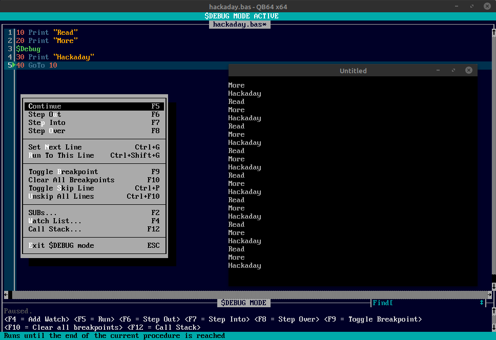
The QB64 team released version 2.0 just a few days ago, making this the perfect time to give the project a test drive if you haven’t tried it out yet. The changelog includes platform specific improvements for each supported operating system, as well as a long list of general fixes and updates. But arguably the biggest feature for this release is the inclusion of the $Debug metacommand.
When this command is included in your code, the IDE will insert a debugging stub into the compiled program. During execution, the QB64 IDE will switch over to debugging mode, and communicate with your program in real-time over a local TCP/IP connection. The debugging mode lets you step through the code line-by-line, check the values of variables, and set breakpoints. Once you’re done fussing with the code and want to release a final binary, you just need to remove that single $Debug command and recompile.
Vises are useful things for holding whatever you’re working on, but too often they’re stuck to a bench. [seamster] has experienced the glory of having a more portable solution, however, and has shared his design for a heavy duty vise tripod that provides just that.
The trick is that to be useful, the design must be heavy and stout enough to hold the vise without tipping over. For this build, [seamster] selected a fat steel pipe with 1/4″ thick walls, some solid bars and some 3/8″ thick plate. Legs and arms where then fabbed up from the bar material and welded up to form the tripod. A stout plate for the vise was then welded on top of the pipe, and the vise mounted pride of place on top.
It’s not a particularly difficult build, but it’s a smart idea that gets you a vise you can easily drag to where it’s needed. If you don’t have the vise itself, consider this hydraulic build. Meanwhile, if you’ve been whipping up your own useful workshop hacks, let us know!
It’s almost hard to remember a time when the obvious answer to most questions about manufacturing wasn’t “Throw it on the CNC.” CNC machines have become so entrenched that the acronym has become a verb; few people would misunderstand a statement like “Let’s just CNC that.”
But before CNC machines became so ubiquitous, there were plenty of clever tricks for cutting material in a controlled fashion, as [Pask] shows us with this tool to machine wood for inlays. The tool is called a parser (or passer) drill, and is designed for use in conjunction with a steel template. [Pask]’s version seems pretty easy to make; a pair of mild steel bars are forged flat into spade shapes before having a cutting surface ground into them. The two halves of the drill are welded together and ground down to fit in the chuck of a hand drill, a modern nod to the fact that few people will want to use the traditional bow and breastplate that drove the original parser drills.
In use, a steel template that determines the shape of the inlay is affixed to the workpiece. The cutting edges of the bits are plunged into the template cutout to machine out the wood; the overhangs of the bits act as depth stop and guide. It only takes a few seconds to make a neat, CNC-free inlay. The video below shows the tool being made and in action.
It’s nice to see what can be accomplished without the need for fancy CNC machines. Not that we have anything against them, of course, but when the same results can be had with some scraps of steel and a little ingenuity, it’s pretty impressive. Looking for something between manual tools and CNC for woodworking? The pantorouter might be just your speed.
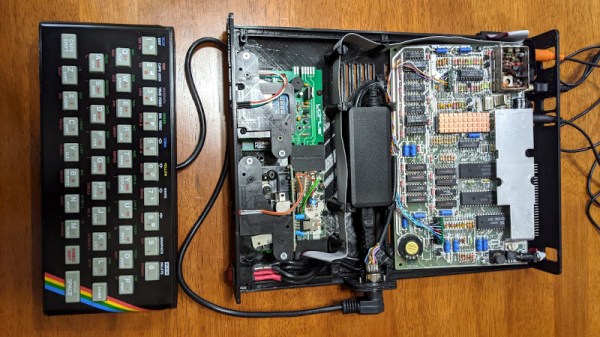
Retrocomputer enthusiasts will quite often be found pondering the great what ifs of their hobby. What if Commodore had had a half-way decent marketing division is a popular one, but the notoriously penny-pinching ways of Sinclair Research are also a plentiful source. What if Sinclair had won the competition for a computer in UK schools, not only the first time around when Acorn’s BBC Micro scooped the prize, but also what if they’d entered the fray once more in 1983 when there was another chance? [10p6] investigates this possibility, and comes up with a Spectrum desktop computer that you can see in the video below the break.
The first two-thirds of the video is devoted to renders which, while pretty to look at, offer nothing of substance. In the later part though we see a build, putting a Spectrum 48k board, Interface 1, and two Microdrives in a slimline case along with a power supply. Meanwhile a ZX rubber keyboard is mounted stand-alone on the end of a cable. It’s a computer that we know would have been an object of desire for many kids back in the day, and we agree with the video that it could have been integrated onto one board without the need for a separate Interface 1. We feel it’s inevitable though that Sinclair’s cost-cutting would have caused something to go astray and there would certainly have been only one Microdrive, even though we like that separate keyboard a lot.
They claim that the STLs will be available from a Facebook group, however unless you happen to have a set of Microdrives and an Interface 1 to go with your Spectrum that you’re prepared to butcher for the project we’re guessing that the chief interest lies in watching it unfold and that some of the ideas might translate to other platforms. Meanwhile if you’re interested in the Microdrive, we did a teardown on them last year.
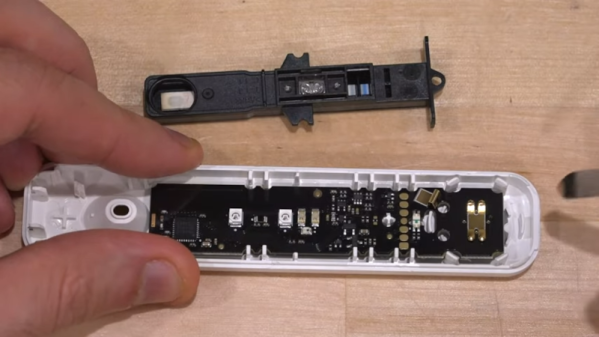
The latest video from [TheSignalPath] is a result of his purchase of a home COVID-19 test. He found an electronic version that connects to your cell phone and displays the results on the phone. The device is an antigen test and, internally, works like the home tests that show the results using lines similar to a pregnancy test. So, somehow, the phone version reads the lines and communicates with the phone. But how? That’s the point of the video, which you can see below.
In a traditional test, there’s a control line that has to appear to show that the test was done correctly. Then a line under that indicates detection of the virus. The circuit board inside the electronic test has a plastic unit onboard that contains a similar strip and has optical sensors for both the reference line and the detection line. Since it is essentially an optical device — there are some lenses in the strip assembly that look like they are detecting the dye as it moves through the strip with LEDs onboard to shed light on the situation.
Under the microscope, the CPU is a typical Bluetooth-capable ARM chip from Nordic. The board did power up, but the device is made to only operate once because of the test strip. The video notes — and we agree — it seems wasteful to create an entire Bluetooth-enabled microcontroller board with optical components just to read a strip one time that is pretty easy to read to start with. We’ll stick with the simple test strip. Still, it is interesting to see the insides.
If you want to read more about antigen tests, we covered that. We also talked about PCR testing.