To find your position on the earth’s surface there are a variety of satellite-based navigation systems in orbit above us, and many receiver chipsets found in mobile phones and the like can use more than one of them. Should you not wish to be tied to a system produced by a national government though, there’s now an alternative. It comes not from an official source though, but as a side-effect of something else. Researchers at Ohio State University have used the Starlink satellite broadband constellation to derive positional fixing, achieving a claimed 8-metre accuracy.
The press release is light on information about the algorithm used, but since it mentions that it relies on having advance knowledge of the position and speed of each satellite we’re guessing that it measures the Doppler shift of each satellite’s signal during a pass to determine a relative position which can be refined by subsequent observations of other Starlink craft.
The most interesting takeaway is that while this technique leverages the Starlink network, it doesn’t have any connection to the service itself. Instead it’s an entirely passive use of the satellites, and though its accuracy is around an order of magnitude less than that achievable under GPS it delivers a position fix still useful enough to fit the purposes of plenty of users.
A radio receiver is always a fun project. [Jayakody2000lk] decided that his new superheterodyne design would use an Arduino and it looks like it came out very nicely. The system has four boards. An off-the-shelf Arduino, a Si5351 clock generator board (also off-the-shelf), and two custom boards that contain the IF amplifier and mixer.
The receiver started out in 2015 without the Arduino, and there’s a link in the post to that original design. Using the Si5351 and the Arduino replaces the original local oscillator and there have been other improvements, as well. You can see a video about the receiver below.
Tuning is by a rotary encoder and the current software lets you tune from about 4.75 MHz to a little over 15.8 MHz. Of course, you could change to any frequency the Si5351 can handle as long as the mixer and other components can handle it. The IF frequency is the usual 455 kHz.
If you decide to build this yourself, the design files are on GitHub. Overall a very nice and neat design. We are always amazed how little radio architecture has changed since Edwin Armstrong’s day. Of course, we have better components, even if they aren’t meant for radio purposes.
We have to admit, it was hard not to be insufferably smug this week when Facebook temporarily went dark around the globe. Sick of being stalked by crazy aunts and cousins, I opted out of that little slice of cyber-hell at least a decade ago, so Monday’s outage was no skin off my teeth. But it was nice to see that the world didn’t stop turning. More interesting are the technical postmortems on the outage, particularly this great analysis by the good folks at the University of Nottingham. Dr. Steve Bagley does a great job explaining how Facebook likely pushed a configuration change to the Border Gateway Protocol (BGP) that propagated through the Internet and eventually erased all routes to Facebook’s servers from the DNS system. He also uses a graphical map of routes to show peer-to-peer connections to Facebook dropping one at a time, until their machines were totally isolated. He also offers speculation on why Facebook engineers were denied internal access, sometimes physically, to their own systems.
It may be a couple of decades overdue, but the US Federal Communications Commission finally decided to allow FM voice transmissions on Citizen’s Band radios. It seems odd to be messing around with a radio service whose heyday was in the 1970s, but Cobra, the CB radio manufacturer, petitioned for a rule change to allow frequency modulation in addition to the standard amplitude modulation that’s currently mandatory. It’s hard to say how this will improve the CB user experience, which last time we checked is a horrifying mix of shouting, screaming voices often with a weird echo effect, all put through powerful — and illegal — linear amps that distort the signal beyond intelligibility. We can’t see how a little less static is going to improve that.
Can you steal a car with a Game Boy? Probably not, but car thieves in the UK are using some sort of device hidden in a Game Boy case to boost expensive cars. A group of three men in Yorkshire used the device, which supposedly cost £20,000 ($27,000), to wirelessly defeat the security systems on cars in seconds. They stole cars for garages and driveways to the tune of £180,000 — not a bad return on their investment. It’s not clear how the device works, but we’d love to find out — for science, of course.
There have been tons of stories lately about all the things AI is good for, and all the magical promises it will deliver on given enough time. And it may well, but we’re still early enough in the AI hype curve to take everything we see with a grain of salt. However, one area that bears watching is the ability of AI to help fill in the gaps left when an artist is struck down before completing their work. And perhaps no artist left so much on the table as Ludwig von Beethoven, with his famous unfinished 10th Symphony. When the German composer died, he had left only a few notes on what he wanted to do with the four-movement symphony. But those notes, along with a rich body of other works and deep knowledge of the composer’s creative process, have allowed a team of musicologists and AI experts to complete the 10th Symphony. The article contains a lot of technical detail, both on the musical and the informatics sides. How will it sound? Here’s a preview:
And finally, Captain Kirk is finally getting to space. William Shatner, who played captain — and later admiral — James Tiberius Kirk from the 1960s to the 1990s, will head to space aboard Blue Origin’s New Shepard rocket on Tuesday. At 90 years old, Shatner will edge out Wally Funk, who recently set the record after her Blue Origin flight at the age of 82. It’s interesting that Shatner agreed to go, since he is said to have previously refused the offer of a ride upstairs with Virgin Galactic. Whatever the reason for the change of heart, here’s hoping the flight goes well.
Those of us tasked with developing firmware for embedded systems have a quite a few hurdles to jump through compared to those writing for the desktop or mobile platforms. Solved problems such as code reuse or portability are simply harder. It was with considerable interest that we learnt of another approach to hardware abstraction, called Luos, which describes itself as micro-services for embedded systems.
This open source project enables deployment of distributed architectures composed of collaborating micro-services. By containerizing applications and hardware drivers, interfaces to the various components are hidden behind a consistent API. It doesn’t even matter where a resource is located, multiple services may be running on the same microcontroller, or separate ones, yet they can communicate in the same way.
By following hardware and software design rules, it’s possible to create an architecture of cooperating computing units, that’s completely agnostic of the actual hardware. Microcontrollers talk at the hardware level with a pair of bidirectional signals, so the hardware cost is very low. It even integrates with ROS, so making robots is even easier.
Luos architecture
By integrating a special block referred to as a Gate, it is possible to connect to the architecture in real-time from a host computer via USB, WiFi, or serial port, and stream data out, feed data in, or deploy new software. The host software stack is based around Python, running under Jupyter Notebook, which we absolutely love.
Current compatibility is with many STM32 and ATSAM21 micros, so chances are good you can use it with whatever you have lying around, but more platforms are promised for the future.
Now yes, we’re aware of CMSIS, and the idea of Hardware Abstraction Layers (HALs) used as part of the platform-specific software kits, this is nothing new. But, different platforms work quite differently, and porting code from one to another, just because you can no longer get your preferred microcontroller any more, is a real drag we could all do without, so why not go clone the GitHub and have a look for yourselves?
One of the greatest challenges for a hardware hacker relying only on a bicycle for transport lies in the regular need to carry more than can be slung from the handlebars or on the luggage rack of your trusty steed. One of our favourite YouTube creators in our sphere, [Laura Kampf], has addressed this problem with a trailer for her electric bike made from a pair of second-hand wheelbarrows. She uses their buckets to make a clamshell box, and their wheels alongside a custom steel chassis to make the rest of the trailer.
As always with Laura’s work it’s a delight to watch, with some careful use of the cutting wheel to install hinges and vents in the upper bucket. Finishing touches are a chequer plate top for the trailer and a spare wheel mounted on the back for that extra-rugged look. Experience with wheelbarrow wheels suggests to us that the slightly more expensive ones with ball bearings are worth the investment over the plastic ones, but either way this is a bike trailer that means business.
We don’t see as many bike trailers as we’d like here at Hackaday, and those few we have are old enough to have succumbed to link-rot. Perhaps this project might tempt a few people to try their hand?
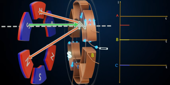
In the everything old is new again folder, [Lesics] has a good overview of axial flux motors. These are promising for electric vehicles, especially aircraft, since the motors should have high torque to weight ratio. The reason this is actually something old is that the early generators built by Faraday were actually of the axial flux type. Soon, though, radial flux generators and motors became the norm.
The simple explanation is that in a radial system, the magnetic flux lines are perpendicular to the axis of rotation. In the axial system, the flux lines are parallel to the axis of rotation. There’s more to it than just that of course, and the video below has nice animations showing how it all works.
While these are not very common, they do exist even today. The Lynch motor, for example, is a type of axial flux motor that dates back to 1979. Usually, the impetus for using an axial flux motor is the ease of construction, but with the right design, they can be quite efficient (up to 96% according to the video).
We’ve seen plenty of PCB motors and most of those are axial in design. Not all of them, though.
Ground effect vehicles, or ekranoplans, have the advantage of being more efficient than normal aircraft and faster than boats, but so far haven’t been developed beyond experimental prototypes. Fortunately, this doesn’t stop companies from trying, which has led to a collaboration between [ThinkFlight] and [rctestflight] to create a small-scale demonstrator for the Flying Ship Company.
The Flying Ship Company wants to use unmanned electric ekranoplans as high-speed marine cargo carriers that can use existing maritime infrastructure for loading and unloading. For the scale model, [rctestflight] was responsible for the electronics and software, while [ThinkFlight] built the airframe. As with his previous ekranoplan build, [ThinkFlight] designed it in XFLR5, cut the parts from foam using a CNC hot wire cutter (which we still want a better look at), and laminated it with Kevlar for strength. One of the challenges of ground effect vehicles is that the center of pressure will shift rearward as they leave a ground effect, causing them to pitch up. To maintain control when moving into and out of ground effect, these crafts often use a large horizontal stabilizer high up on the tail, out of ground effect.
A major feature of this demonstrator is automatic altitude control using a LIDAR sensor mounted on the bottom. This was developed by [rctestflight] using a simple foam board ekranoplan and [Think Flighs]’s previous airframe, with some custom code added to ArduPilot. It works very well on smooth, calm water, but waves introduce a lot of noise into the LIDAR data. It looks like they were able to overcome this challenge, and completed several successful test flights in calm and rough conditions.
The final product looks good, flies smoothly, and is easy to control since the pilot doesn’t need to worry about pitch or throttle control. It remains to be seen if The Flying Boat will overcome the challenges required to turn it into a successful commercial craft, and we will be following the project closely.