Everyone loves watching movies, that is, so long as you can hear what the characters on screen are saying. [GreatScott] found this second part difficult while watching through BladeRunner 2049, so he designed an automatic volume adjuster to assist.
At a high level, the solution is fairly straightforward; when there is loud music playing in a movie, turn the volume down. The challenge is how to actually achieve that. The first step was controlling the volume. To avoid having to modify or damage his sound system, [GreatScott] opted instead to mimic the volume up and down signals of his remote over IR. Using the very handy IRremote library for Arduino and its built-in decoding functionality, he was able to identify and replicate the signals with his own IR LED.
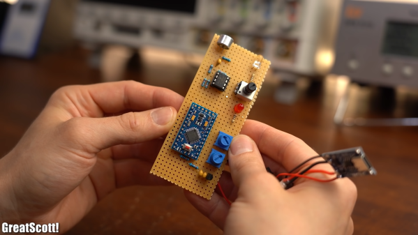
The second step in this process was measuring the volume of the movie. [GreatScott] achieved this with a microphone and amplifier circuit, that was then piped into one of the analog pins of the Arduino Pro Micro at the heart of the build. Since the audio being sampled could have a frequency as high as 20 kHz, the ADC Prescaler had to be adjusted from its standard value, which would have only permitted measurements at less than 5 kHz.
The third step was writing the algorithm to detect loud music and adjust the volume accordingly. The Arduino will measure the audio until a sound greater than the dead band value, set with one of the two onboard potentiometers, is detected. This then triggers the Arduino to start a timer, to see how frequently the upper limit is being surpassed. If it is just one or two occasionally loud noises (like a scream, a clap, whistling, etc.) the Arduino will not take any action, but multiple loud noises in rapid succession will then trigger the volume down command over the IR LED. A second potentiometer allows for adjustment of this timer’s critical value, so that you can make the system respond faster or slower depending on the movie.
Once the sound has been detected to have dropped down below a critical vaue, the Arduino assumes that the movie is back to dialog and will increase the volume by the number of times it decreased it before, leaving you back at the perfect volume.
Maybe you’re the type that cares more for the visuals of a movie, rather than the audio. In that case, this e-paper movie display will be perfect for giving you time to appreciate every frame!
Continue reading “Is Your Movie Too Loud? Can’t Hear The Dialogue? This Circuit Can Help.” →