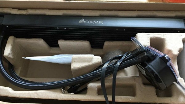
What can you do if you have a nice piece of hardware that kinda works out of the box, but doesn’t have support for your operating system to get the full functionality out of it? [Harry Gill] found himself in such a situation with a new all-in-one (AIO) water cooling system. It didn’t technically require any operating system interaction to perform its main task, but things like settings adjustments or reading back statistics were only possible with Windows. He thought it would be nice to have those features in Linux as well, and as the communication is done via USB, figured the obvious solution is to reverse engineer the protocol and simply replicate it.
His first step was to set up a dual boot system (his attempts at running the software in a VM didn’t go very well) which allowed him to capture the USB traffic with Wireshark and USBPcap. Then it would simply be a matter of analyzing the captures and writing some Linux software to make sense of the data. The go-to library for USB tasks would be libusb, which has bindings for plenty of languages, but as an avid Rust user, that choice was never really an issue anyway.
How to actually make use of the captured data was an entirely different story though, and without documentation or much help from the vendor, [Harry] resorted to good old trial and error to find out which byte does what. Eventually he succeeded and was able to get the additional features he wanted supported in Linux — check out the final code in the GitHub repository if you’re curious what this looks like in Rust.
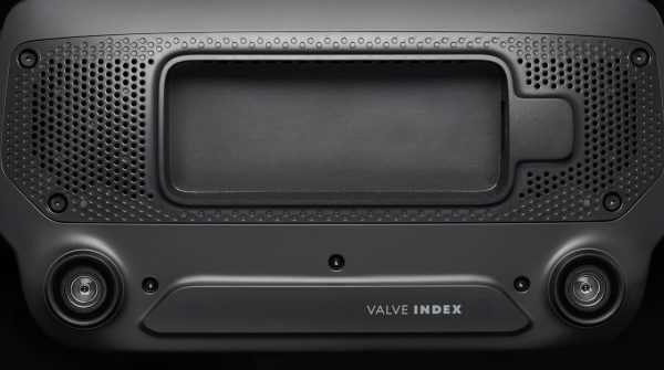
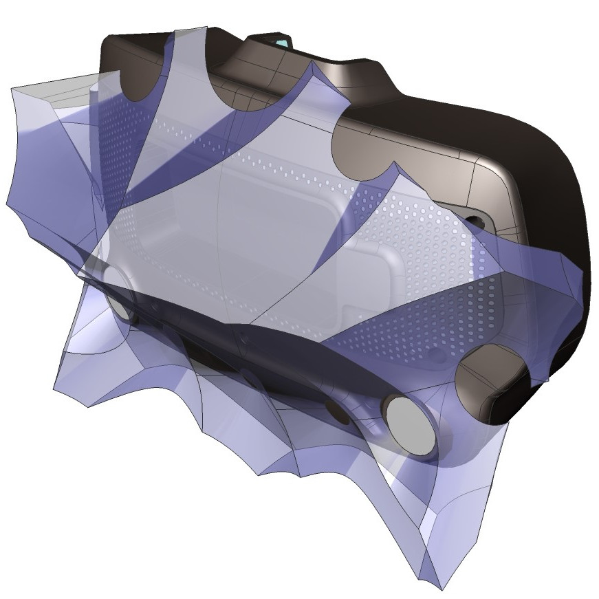
It’s been just over a year since Valve released Index, their flagship VR system, and it’s worth looking back at this GitHub repository as a fine example of how to provide supporting materials to a hacker-friendly hardware design. The image above shows off one of the hacker-friendly design elements: an empty space behind the visor, with a USB port off to the right, that exists for no reason other than to make it easier to mount and plug in whatever one might come up with. There’s more to it than that, however. If one wishes to provide supporting materials for a hardware design, one could certainly do worse than emulate Valve’s example.
The violet 3D model shows the area that modifications can occupy without getting in the way of any sensors.
The hardware repository contains not just CAD models of mod-friendly hardware pieces (both in high-resolution STEP models as well as STL files) but also 3D models of the sensor zones, so modders can ensure they avoid occluding any sensors with their creations. Examples are great, and one provided by Valve is the Booster; a hand controller add-on providing extra comfort for people with large hands or long thumbs. The model also doubles as a reference for designing attachments that will not interfere with any of the tracking or touch-sensitive surfaces of the controllers.
Being hacker-friendly doesn’t mean the hardware has no warranty, but it does mean that there is concrete guidance on what does or doesn’t risk voiding it. In the case of the Index hardware, the guidance is simple: “Anything that requires a T5 or smaller is not user serviceable.”
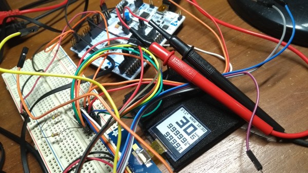
A typical bicycle computer from the store rack will show your speed, trip distance, odometer, and maybe the time. We can derive all this data from a magnet sensor and a clock, but we live in a world with all kinds of sensors at our disposal. [Matias N.] has the drive to put some of them into a tidy yet competent bike computer that has a compass, temperature, and barometric pressure.
The brains are an STM32L476 low-power controller, and there is a Sharp Memory LCD display as it is a nice compromise between fast refresh rate and low power. E-paper would be a nice choice for outdoor readability (and obviously low power as well) but nothing worse than a laggy speedometer or compass.
In a show of self-restraint, he didn’t try to replace his mobile phone, so there is no GPS, WiFi, or streaming music. Unlike his trusty phone, you measure the battery life in weeks, plural. He implemented EEPROM memory for persistent data through power cycles, and the water-resistant board includes a battery charging circuit for easy topping off between rides.
If you wanted me to demo CP/M running on an emulated Altair 8800, I’d pull out a tiny board from my pocket. You might wonder how I wound up with an Altair 8800 that runs CP/M (even WordStar), that fits in your pocket and cost less than $10. Turns out it’s a story that goes back to 1975.
When the Altair 8800 arrived back in 1975, I wanted one. Badly. I’d been reading about computers but had no hands-on experience. But back then, as far as I was concerned, the $400 price tag might as well have been a million bucks. I was working for no real pay in my family’s store, though in all fairness, adjusted into today’s money that was about $2,000.
I’d love to buy one now, but a real Altair costs even more today than it did back then. They also take up a lot of desk space. Sure, there are replicas and I’ve had a few. I even helped work the kinks out of Vince Briel’s clone which I’ve enjoyed. However, the Briel computer has two problems. First, it takes a little work to drive a serial port (it uses a VGA and a PS/2 keyboard). Second, while it’s smaller than a real Altair, it is still pretty large — a byproduct of its beautiful front panel.
So to quickly show off CP/M to someone, you need to haul out a big box and find a VGA monitor and PS/2 keyboard — both of which are becoming vanishing commodities. I made some modifications to get the serial port working, but it is still a lot to cart around. You could go the software route with a simulator like SIMH or Z80pack, but now instead of finding a VGA monitor and a PS/2 keyboard, you need to find a computer where you can install the software. What I really wanted was a simple and portable device that could boot CP/M.
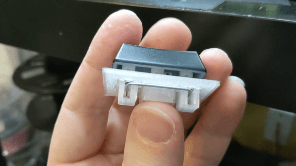
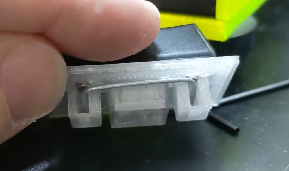
Keyboard key stabilizers, or stabs as they’re known in enthusiast circles, do exactly what you’d expect — they stabilize longer keys like the Shifts and the space bar so that they don’t have to be struck dead-center to actuate evenly. Stabs work by flanking the key switch with two non-functional switch actuators linked with a thick wire bar. Some people love stabs and insist on stabilizing every key that’s bigger than 1u, while other people think stabs are more trouble than they’re worth for various reasons, like rattling.
Although the print is an easy one, [Riskable] says the design process wasn’t as cut and dried as it seems. The center points of the stabilizer stems aren’t supposed to be in the center of cutouts, even though it looks that way to the naked eye. After that, the pain point has shifted to the wire, and getting it as straight as possible before making the necessary bends. [Riskable] is going to make a straightener to help out, and we suggest something like this one.
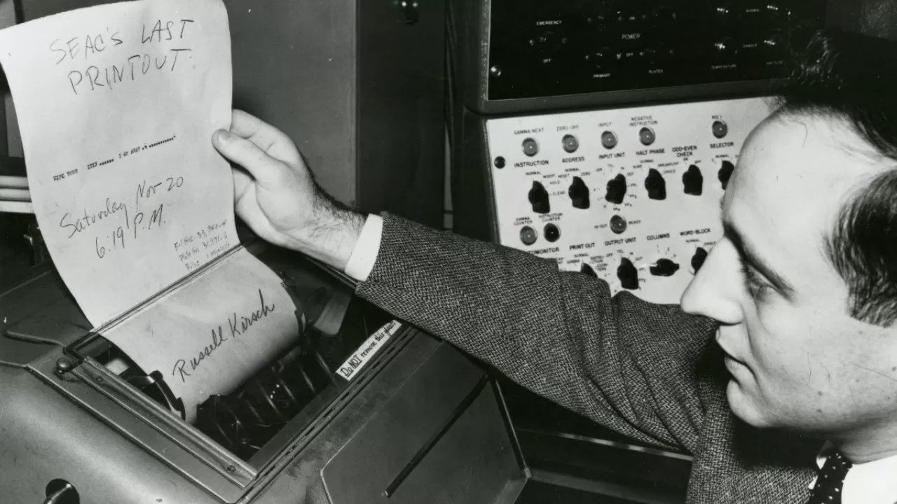
It’s true what they say — you never know what you can do until you try. Russell Kirsch, who developed the first digital image scanner and subsequently invented the pixel, was a firm believer in this axiom. And if Russell had never tried to get a picture of his three-month-old son into a computer back in 1957, you might be reading Hackaday in print right now. Russell’s work laid the foundation for the algorithms and storage methods that make digital imaging what it is today.
Russell reads SEAC’s last printout. Image via TechSpot
Russell A. Kirsch was born June 20, 1929 in New York City, the son of Russian and Hungarian immigrants. He got quite an education, beginning at Bronx High School of Science. Then he earned a bachelor’s of Electrical Engineering at NYU, a Master of Science from Harvard, and attended American University and MIT.
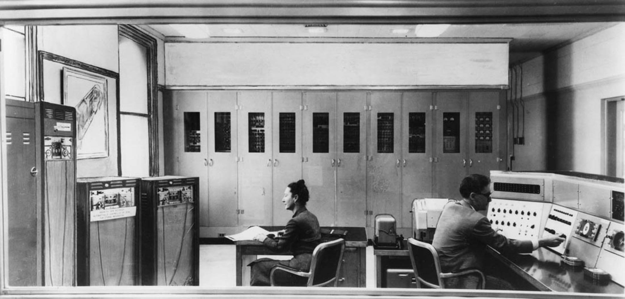
In 1951, Russell went to work for the National Bureau of Standards, now known as the National Institutes of Science and Technology (NIST). He spent nearly 50 years at NIST, and started out by working with one of the first programmable computers in America known as SEAC (Standards Eastern Automatic Computer). This room-sized computer built in 1950 was developed as an interim solution for the Census Bureau to do research (PDF).
Standards Eastern Automatic Computer (SEAC) was the first programmable computer in the United States. Credit: NIST via Wikimedia
Like the other computers of its time, SEAC spoke the language of punch cards, mercury memory, and wire storage. Russell Kirsch and his team were tasked with finding a way to feed pictorial data into the machine without any prior processing. Since the computer was supposed to be temporary, its use wasn’t as tightly controlled as other computers. Although it ran 24/7 and got plenty of use, SEAC was more accessible than other computers, which allowed time for bleeding edge experimentation. NIST ended up keeping SEAC around for the next thirteen years, until 1963.
The Original Pixel Pusher
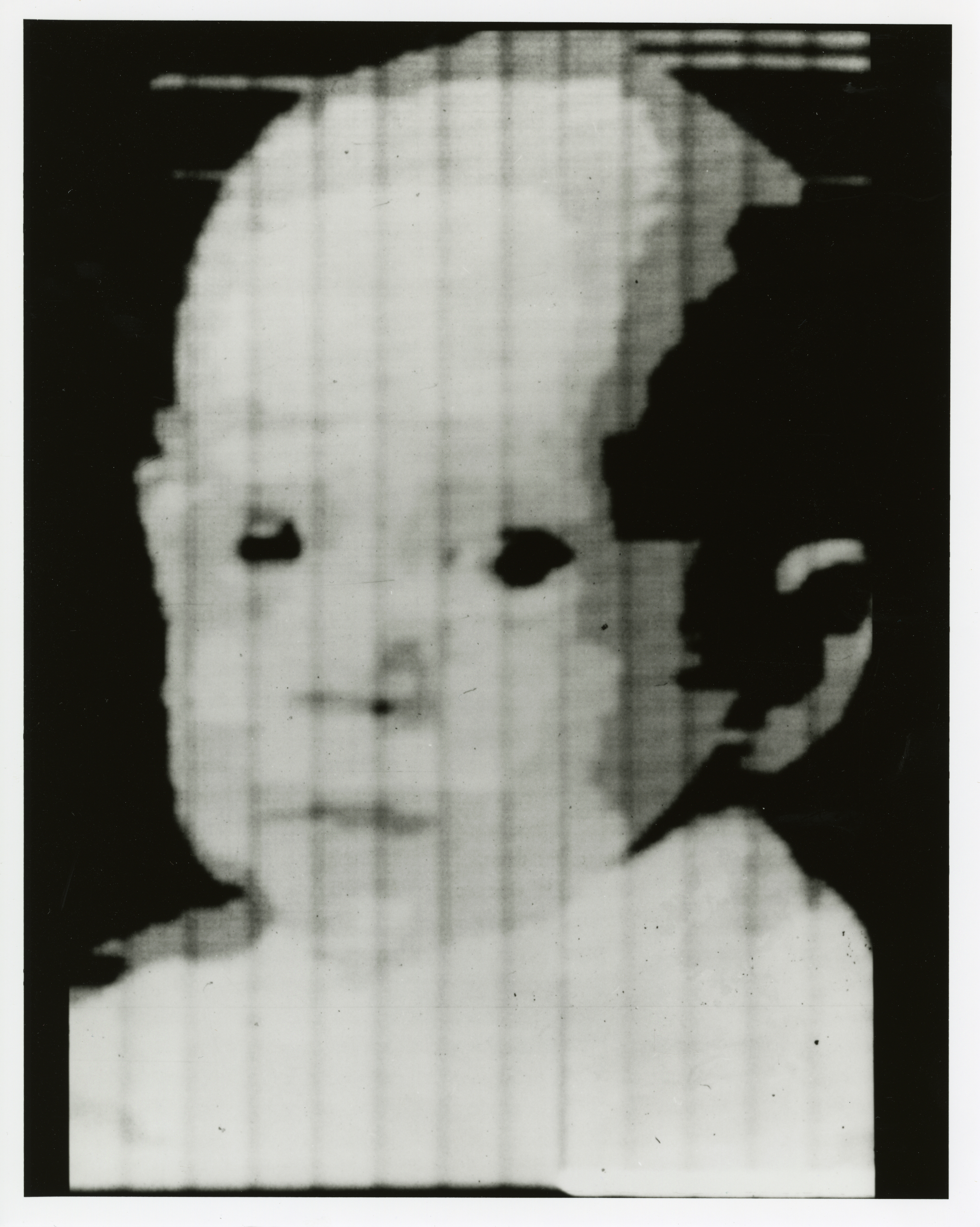
This photo of Russell’s son Walden is the first digitized image. Public Domain via Wikimedia
The term ‘pixel’ is a shortened portmanteau of picture element. Technically speaking, pixels are the unit of length for digital imaging. Pixels are building blocks for anything that can be displayed on a computer screen, so they’re kind of the first addressable blinkenlights.
As the drum slowly rotated, a photo-multiplier moved back and forth, scanning the image through a square viewing hole in the wall of a box. The tube digitized the picture by transmitting ones and zeros to SEAC that described what it saw through the square viewing hole — 1 for white, and 0 for black. The digital image of Walden is 76 x 76 pixels, which was the maximum allowed by SEAC.
In in the video below, Russell discusses the idea and proves that variable pixels make a better image with more information than square pixels do, and with significantly fewer pixels overall. It takes some finagling, as pixel pairs of triangles and rectangles must be carefully chosen, rotated, and mixed together to best represent the image, but the image quality is definitely worth the effort. Following that is a video of Russell discussing SEAC’s hardware.
Russell retired from NIST in 2001 and moved to Portland, Oregon. As of 2012, he could be found in the occasional coffeehouse, discussing technology with anyone he could engage. Unfortunately, Russell developed Alzheimer’s and died from complications on August 11, 2020. He was 91 years old.
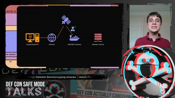
Geosynchronous satellites, girdling the Earth from their perches 36,000 km above the equator, are remarkably useful devices. Depending on where they’re parked, they command views of perhaps a third of the globe at a time, making them perfect communications relays. But as [James Pavur] points out in his DEF CON Safe Mode talk, “Whispers Among the Stars”, geosynchronous satellite communication links are often far from secure.
[James], a D. Phil. student in Systems Security at Oxford University, relates that his exploits rely on the wide areas covered by the downlink signals from the satellites, coupled with security as an afterthought, if it was even thought of at all by satellite service providers. This lackadaisical approach let him use little more than a regular digital satellite TV dish and a tuner card for a PC — off-the-shelf stuff that you’d really have to try hard to spend more than $300 on — to tap into sensitive information.
While decoding the digital signals from satellites into something parseable can be done with commercial applications, [James] and his colleagues built a custom tool, GSExtract, to pull data from the often noisy signals coming down from on high. The setup returned an amazing bounty of information, like maritime operators relaying the passport information of crew members from ship to shore, point-of-sale terminal information from cruise ships in the Mediterranean, and in-flight entertainment systems in jet airliners. The last example proved particularly alarming, as it revealed an exploitable connection between the systems dedicated to keeping passengers content and those in the cockpit, which clearly should not be the case.
We found [James’] insights on these weaknesses in satellite communications fascinating, and it’s well worth the 45 minutes to watch the video below and perhaps try these exploits, which amount to side-channel attacks, for yourself.
 The brains are an STM32L476 low-power controller, and there is a Sharp Memory LCD display as it is a nice compromise between fast refresh rate and low power. E-paper would be a nice choice for outdoor readability (and obviously low power as well) but nothing worse than a laggy speedometer or compass.