When Lego introduced its Mindstorms line in 1998, in a lot of ways it was like a gateway drug into the world of STEM, even though that term wouldn’t be invented for another couple of years. Children and the obsolete children who begat them drooled over the possibility of combining the Lego building system with motors, sensors, and a real computer that was far and away beyond anything that was available at the time. Mindstorms became hugely influential in the early maker scene and was slowly but steadily updated over the decades, culminating with the recently released Mindstorms Robot Inventor kit. In the thirteen years since the last release, a lot has changed in the market, and we Hackaday scribes had a discussion this week about the continued relevancy of Mindstorms in a time when cheap servos, microcontrollers, and a bewildering array of sensors can be had for pennies. We wonder what the readers think: is a kit that burns a $360 hole in your pocket still worth it? Sound off below.
Are you looking for a way to productively fill some spare time? Plenty of people are these days, and Hackaday has quite a deal for them: Hackaday U! This series of online courses will get you up to speed on a wide range of topics, starting tomorrow with Matthew Alt’s course on reverse engineering with Ghidra. Classes meet online once a week for four weeks, with virtual office hours to help you master the topic. Beside reverse engineering, you can learn about KiCad and FreeCad, quantum computing, real-time processing of audio and sensor data, and later in the year, basic circuit theory. We’ve got other courses lined up to fill out the year, but don’t wait — sign up now! Oh, and the best part? It’s on a pay-as-you-wish basis, with all proceeds going to charity. Get smarter, help others while doing it — what’s not to love about that?
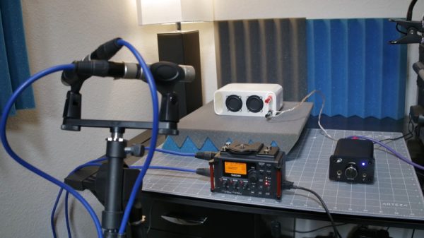
Speaking of virtual learning, the GNU Radio Conference will be moving online for its 10th anniversary year. And while it’s good news that this and other cons have been able to retool and continue their mission of educating and growing this community, it’s still a bummer that there won’t be a chance to network and participate in all the fun events such cons offer. Or perhaps there will — it seems like the Wireless Capture the Flag (CTF) event is still going to happen. Billed as “an immersive plot-driven … competition featuring the GNU Radio framework and many other open-source tools, satellite communications, cryptography, and surreal global landscapes,” it certainly sounds like fun. We’d love to find out exactly how this CTF competition will work.
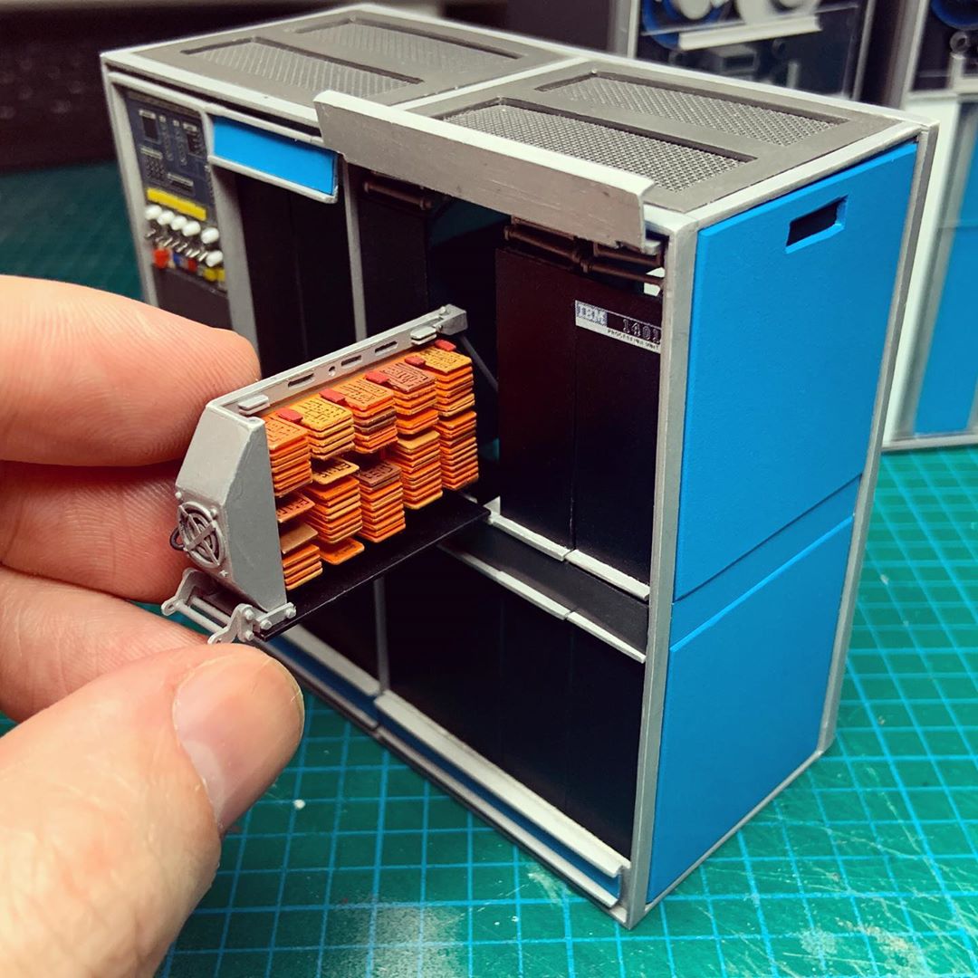
 Everyone needs a way to unwind, and sometimes the best way to do that is to throw yourself into a project of such intricacy and delicate work that you’re forced into an almost meditative state by it. We’ve seen beautiful examples of that with the wonderful circuit sculptures of Mohit Bhoite and Jiří Praus, but here’s something that almost defies belief: a painstakingly detailed diorama of a vintage IBM data center. Created by the aptly named [minatua], each piece of this sculpture is a work of art in its own right and represents the “big iron” of the 1400 series of computers from the early 1960s. The level of detail is phenomenal — the green and white striped fanfold paper coming out of the 1403 line printer has tiny characters printed on it, and on the 729 tape drives, the reels spin and the lights flash. It’s incredible, all the more so because there don’t appear to be any 3D-printed parts — everything is scratch built from raw materials. Check it out.
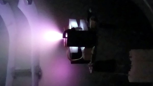
As you can imagine, the Hackaday tip line attracts a fair number of ideas of the scientifically marginal variety. Although we’re not too fond of spammers, we try to be kind to everyone who bothers to send us a tip, but with a skeptical eye when terms like “free energy” come across. Still, we found this video touting to Nikola Tesla’s free energy secrets worth passing on. It’s just how we roll.
And finally, aside from being the first full day of summer, today is Father’s Day. We just want to say Happy Father’s Day to all the dads out there, both those that inspired and guided us as we were growing up, and those who are currently passing the torch to the next generation. It’s not easy to do sometimes, but tackling a project with a kid is immensely important work, and hats off to all the dads who make the time for it.