PCB Metro Maps Are A Gorgeous Labor Of Love

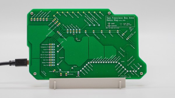
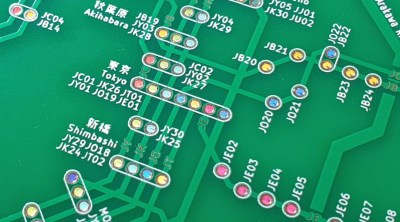
Is your love of public transportation matched only by your passion for designing custom PCBs? If so, then you’re going to love these phenomenal transit maps created by [Chai Jia Xun]. Using the painstakingly refined principles outlined in his detailed write-up, he’s created versions for Tokyo, Singapore, and the comparatively spartan San Francisco Bay Area. All you need to make one up for your home town is an incredible amount of patience and dedication. No problem, right?

As [Xun] explains, the first part of creating one of these maps isn’t unlike generating a normal PCB. Just make a footprint for the stations, consult with Google Maps as to where they should be placed on the board, and then connect them all up with traces to stand in for the rail lines. A little silkscreen work, and you’re done.

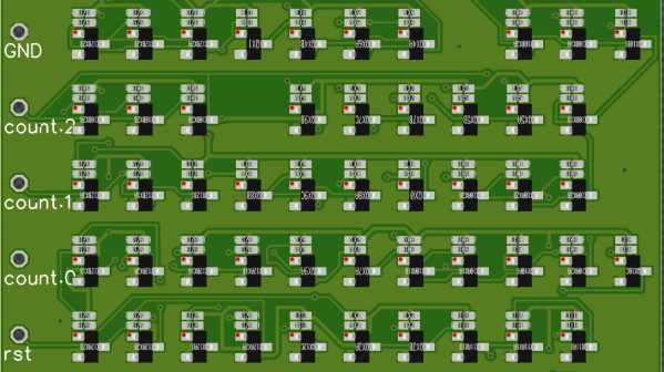
Well…unless you want them to light up, anyway. To pull that off, [Xun] created a second PCB that places an LED behind each station hole drilled in the previous board. With a microcontroller and shift register, he’s able to selectively illuminate individual lines and run through different patterns. To combat light bleeding through the PCB, a CNC-cut piece of 3 mm MDF sits between the two boards to make sure each LED is only visible through the respective hole in the top surface.

You could call the map finished here as well, assuming you don’t mind all the stations lighting up white. If you want them to be different colors, you’ll need to insert some colored diffusers. [Xun] went through several different approaches here, but in the end, the idea that seemed to work best was to simply print out all the colored dots on a piece of transparency paper and use a second sheet of tracing paper to soften the light. Alignment here is critical, but once everything is dialed in, the results are quite impressive.

It’s quite a bit of work, and we haven’t even mentioned the fact that [Xun] had to modify the circuit when it came time to do the Tokyo map, as some MOSFETs had to be added into the mix for the microcontroller to reliably control 350+ LEDs. So there’s certainly no shame in simply buying one of them when they go on sale instead of trying to recreate it from scratch. Assuming you live in one of the cities he’s offering, anyway. Otherwise, you might want to take a look at our HackadayU class on KiCad and get yourself a comfortable chair.

Recreating The Mac SE Logic Board

When [Kai Robinson] found himself faced with the difficult task of saving as many Mac SE’s as he possibly could, the logical but daunting answer was to recreate the Mac SE logic board for machines that would otherwise be scrapped. These machines are over 30 years old and the PRAM battery often leaks, destroying parts and traces. Given that the logic board is a simple through-hole two four-layer board, how hard could it be?

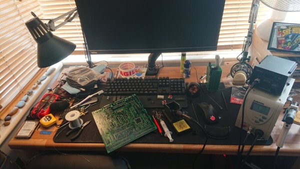
The first step was to get some reference photos so [Kai] set to desoldering everything on the board. The list of components and the age of solder made this an arduous task. Then a composite image was produced by merging images together using a scanner and some Inkscape magic. in graphics software.

Rather than simply putting the pins in the right place and re-routing all the netlists, [Kai] elected instead to do a copy, trace for trace of the original SE board. [Kai] and several others on the forum have been testing the boards and tracking down the last few bugs and kinks in the design. An unconnected pin here and an improperly impedance matched resistor there. Hopefully, soon they’ll have Gerbers and design files ready for anyone should they need a new logic board PCB.

It’s no secret that we love the Macintosh SE here at Hackaday. We’ve seen new custom cases for it and now new PCBs for it. It does cause the mind to ponder though and wonder, what’s next?

Thanks [Toru173] for sending this one in!

A VGA Retro Console With Everything Generated From A Single ARM Cortex M0

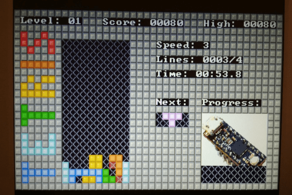
The later game consoles of the 8-bit era such as Nintendo’s NES or Sega’s Master System produced graphics that went beyond what owners of early 1980s home computers had come to expect from machines with the same processors, but they did so only with the help of powerful custom chipsets for their day that took care of the repetitive hard work of assembling frames and feeding them to the display device. Reproducing their equivalent with more modern hardware requires either some means of creating similar custom silicon, or a processor significantly more powerful such that it can do the work of those extra chips itself. But even with a modern microcontroller it’s still a significant challenge, so [Nicola Wrachien]’s uChip, a VGA console that does the whole job in software on a humble ARM Cortex M0 is a significant achievement.

If you are familiar with the home computers that used the processor to generate the display output, you’ll know that they spent most of their time working on the lines of the display and only had a few milliseconds of the frame blanking period for the device to perform any computing tasks before returning to the next frame. The 320×240 at 57 frames per second gives a line sync frequency of 30 kHz, and the computing happens while the display is sent the black space at the top and bottom of the screen. This is reckoned to be equivalent of the ATSAMD21E18 microcontroller on the uChip module the system uses running at only 10MHz rather than the 48MHz it is running at in reality, and with these resources it also runs the game logic, USB controller interfacing, reading games from the SD card, and game sound.

The result is a complete game console on a small PCB little longer on its longest side than its connectors. We may have largely seen the demise of VGA on the desktop several years after we called it, but it seems there is plenty of life in the interface yet for hardware hackers.

Hackaday Podcast 076: Grinding Compression Screws, Scratching PCBs, And Melting Foam

Hackaday editors Elliot Williams and Mike Szczys are enamored by this week’s fabrication hacks. There’s a PCB mill that isolates traces by scratching rather than cutting. You won’t believe how awesome this angle-cutter jig is at creating tapered augers for injection molding/extruding plastic. And you may not need an interactive way to cut foam, but the art from the cut pieces is more than a mere shadow of excellence. Plus we gab about a clever rotary encoder circuit, which IDE is the least frustrating, and the go-to tools for hard drive recovery.

Take a look at the links below if you want to follow along, and as always, tell us what you think about this episode in the comments!

Take a look at the links below if you want to follow along, and as always, tell us what you think about this episode in the comments!

Direct download (60 MB or so.)

Continue reading “Hackaday Podcast 076: Grinding Compression Screws, Scratching PCBs, And Melting Foam”

Recreating Fast Oscilloscopes Is A Slow Process

If you want to do something you’ve never done before, there are two broadly-defined ways of approaching it: either you learn everything you can about it and try to do it right the first time, or you get in there and get your hands dirty, and work out the details along the way. There’s a lot to be said for living life by the seat of your pants. Just ask anyone who found inspiration in the 11th hour of a deadline, simply because they had no other choice.

Ted Yapo didn’t have a lot of high-speed design knowledge when he set out to build an open-source multi-GHz sampling oscilloscope, but he didn’t let that stop him. Fast forward a year or so, and Ted’s ready to build his third prototype armed with all the hands-on practical knowledge he’s gained from building the first two.

At the 2019 Hackaday Superconference, Ted gave a talk about his journey into the high-stakes world of high-speed design. It’s an inspiring talk, and Ted gives a good look into everything he’s learned in trying to build a sampling ‘scope. We think you’ll appreciate not only Ted’s work, but also the ease with which he explains it all.

Continue reading “Recreating Fast Oscilloscopes Is A Slow Process”

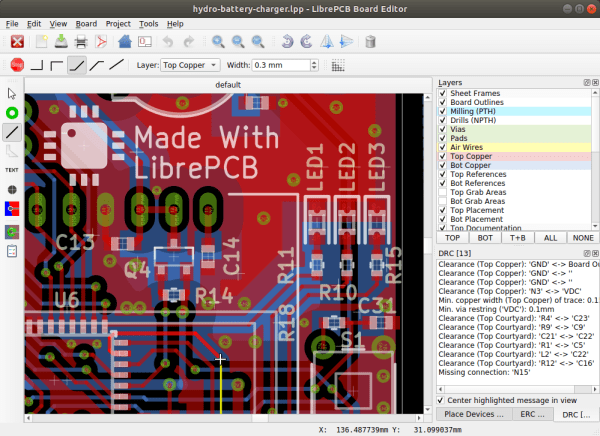
Review: Testdriving LibrePCB Shows That It’s Growing Up Fast

There are a host of PCB CAD tools at the disposal of the electronic designer from entry-level to multi-thousand-dollar workstation software. It’s a field in which most of the players are commercial, and for the open-source devotee there have traditionally been only two choices. Both KiCad and gEDA are venerable packages with legions of devoted fans, but it is fair to say that they both present a steep learning curve for newcomers. There is however another contender in the world of open-source PCB CAD, in the form of the up-and-coming LibrePCB.

This GPL-licensed package has only been in development for a few years. LibrePCB brought out its first official release a little over a year ago, and now stands at version 0.1.3 with builds for GNU/Linux, Windows, MacOS, and FreeBSD. It’s time to download it and run it through its paces, to see whether it’s ready to serve its purpose.

Continue reading “Review: Testdriving LibrePCB Shows That It’s Growing Up Fast”

Reverse Engineer PCBs With SprintLayout

[Bwack] had some scanned pictures of an old Commodore card and wanted to recreate PC boards from it. It’s true that he could have just manually redrawn everything in a CAD package, but that’s tedious. Instead, he used SprintLayout 6.0 which allows you to import pictures and use them as a guide for recreating a PCB layout.

You can see the entire process including straightening the original scans. There are tools that make it very easy to place new structures over the original scanned images.

Continue reading “Reverse Engineer PCBs With SprintLayout”