How Wireless Charging Works And Why It’s Terrible

Wireless charging is pretty convenient, as long as the transmitter and receiver speak the same protocol. Just put the device you want to charge on the wireless charger without worrying about plugging in a cable. Yet as it turns out, the disadvantages of wireless charging may be more severe than you think, at least according to tests by iFixIt’s [Shahram Mokhtari] and colleagues. In the article the basics of wireless charging are covered, as well as why wireless charging wastes a lot more power even when not charging, and why it may damage your device’s battery faster than wired charging.

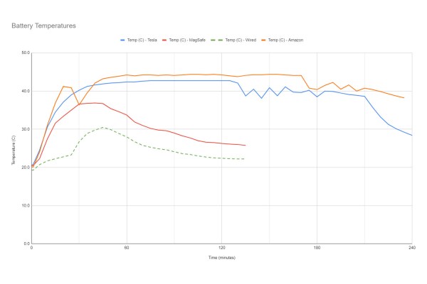
The inefficiency comes mostly from the extra steps needed to create the alternating current (AC) with wireless coupling between the coils, and the conversion back to DC. Yet it is compounded by the issue of misaligned coils, which further introduce inefficiencies. Though various protocols seek to fix this (Qi2 and Apple’s MagSafe) using alignment magnets, these manage to lose 59% of the power drawn from the mains due to these inefficiencies. Wireless chargers also are forced to stay active, polling for a new device to charge, which keeps a MagSafe charger sucking up 0.2 W in standby.

Continue reading “How Wireless Charging Works And Why It’s Terrible”

Human-Interfacing Devices: HID Over I2C

In the previous two HID articles, we talked about stealing HID descriptors, learned about a number of cool tools you can use for HID hacking on Linux, and created a touchscreen device. This time, let’s talk about an underappreciated HID standard, but one that you might be using right now as you’re reading this article – I2C-HID, or HID over I2C.

HID as a protocol can be tunneled over many different channels. If you’ve used a Bluetooth keyboard, for instance, you’ve used tunneled HID. For about ten years now, I2C-HID has been heavily present in laptop space, it was initially used in touchpads, later in touchscreens, and now also in sensor hubs. Yes, you can expose sensor data over HID, and if you have a clamshell (foldable) laptop, that’s how the rotation-determining accelerometer exposes its data to your OS.

This capacitive touchscreen controller is not I2C-HID, even though it is I2C. By [Raymond Spekking], CC-BY-SA 4.0
Not every I2C-connected input device is I2C-HID. For instance, if you’ve seen older tablets with I2C-connected touchscreens, don’t get your hopes up, as they likely don’t use HID – it’s just a complex-ish I2C device, with enough proprietary registers and commands to drive you crazy even if your logic analysis skills are on point. I2C-HID is nowhere near that, and it’s also way better than PS/2 we used before – an x86-only interface with limited capabilities, already almost extinct from even x86 boards, and further threatened in this increasingly RISCy world. I2C-HID is low-power, especially compared to USB, as capable as HID goes, compatible with existing HID software, and ubiquitous enough that you surely already have an I2C port available on your SBC.

In modern world of input devices, I2C-HID is spreading, and the coolest thing is that it’s standardized. The standardization means a lot of great things for us hackers. For one, unlike all of those I2C touchscreen controllers, HID-I2C devices are easier to reuse; as much as information on them might be lacking at the moment, that’s what we’re combating right now as we speak! If you are using a recent laptop, the touchpad is most likely I2C-HID. Today, let’s take a look at converting one of those touchpads to USB HID.

A Hackable Platform

Continue reading “Human-Interfacing Devices: HID Over I2C”

Logic Analyzers: Decoding And Monitoring

Last time, we looked into using a logic analyzer to decode SPI signals of LCD displays, which can help us reuse LCD screens from proprietary systems, or port LCD driver code from one platform to another! If you are to do that, however, you might find a bottleneck – typically, you need to capture a whole bunch of data and then go through it, comparing bytes one by one, which is quite slow. If you have tinkered with Pulseview, you probably have already found an option to export decoded data – all you need to do is right-click on the decoder output and you’ll be presented with a bunch of options to export it. Here’s what you will find:

2521888-2521888 I²C: Address/data: Start
2521896-2521947 I²C: Address/data: Address write: 22
2521947-2521954 I²C: Address/data: Write
2521955-2521962 I²C: Address/data: ACK
2521962-2522020 I²C: Address/data: Data write: 01
2522021-2522028 I²C: Address/data: ACK
2522030-2522030 I²C: Address/data: Start repeat
2522038-2522089 I²C: Address/data: Address read: 22
2522089-2522096 I²C: Address/data: Read
2522096-2522103 I²C: Address/data: ACK
2522104-2522162 I²C: Address/data: Data read: 91
2522162-2522169 I²C: Address/data: NACK
2522172-2522172 I²C: Address/data: Stop

Whether on the screen or in an exported file, the decoder output is not terribly readable – depending on the kind of interface you’re sniffing, be it I2C, UART or SPI, you will get five to ten lines of decoder output for every byte transferred. If you’re getting large amounts of data from your logic analyzer and you want to actually understand what’s happening, this quickly will become a problem – not to mention that scrolling through the Pulseview window is not a comfortable experience.

The above output could look like this: 0x22: read 0x01 ( DEV_ID) = 0x91 (0b10010001). Yet, it doesn’t, and I want to show you how to correct this injustice. Today, we supercharge Pulseview with a few external scripts, and I’ll show you how to transfer large amounts of Sigrok decoder output data into beautiful human-readable transaction printouts. While we’re at it, let’s also check out commandline sigrok, avoiding the Pulseview UI altogether – with sigrok-cli, you can easily create a lightweight program that runs in the background and saves all captured data into a text file, or shows it on a screen in realtime! Continue reading “Logic Analyzers: Decoding And Monitoring”

M17 Digital Communications Go From Strength To Strength

The world of amateur radio is like many other fields in that there has been a move underway from analogue to digital modes. In fact, amateur radio has often led the way in digital innovation.  There’s a snag, though: many of the digital speech modes are proprietary. To address this along comes the M17 project, an effort to create an open digital communication protocol for radio amateurs. We’ve looked at them more than once in the past few years, and as they’ve come up with several pieces of new hardware it’s time for another peek.

First up is the Remote Radio Unit, described as “a comprehensive, UHF FM/M17 “repeater in a box,” optimally designed for close antenna placement, enhancing signal strength and reliability.” The repeater forms the “other half” of the UHF handheld radio chain and will be crucial to the uptake of the protocol.

Continue reading “M17 Digital Communications Go From Strength To Strength”

WSPR To The Wind With A Pi Pico High Altitiude Balloon

They say that if you love something, you should set it free. That doesn’t mean that you should spend any more on it than you have to though, which is why [EngineerGuy314] put together this Raspberry Pi Pico high-altitude balloon tracker that should only set you back about $12 to build.

This simplified package turns a Pico into a tracking beacon — connect a cheap GPS module and solar panel, and the system will transmit the GPS location, system temperature, and other telemetry on the 20-meter band using the Weak Signal Propagation Reporter (WSPR) protocol. Do it right, and you can track your balloon as it goes around the world.

The project is based in part on the work of [Roman Piksayin] in his Pico-WSPR-TX package (which we covered before), which uses the Pico’s outputs to create the transmitted signal directly without needing an external radio. [EngineerGuy314] took this a step further by slowing down the Pico and doing some clever stuff to make it run a bit more reliably directly from the solar panel.

The system can be a bit fussy about power when starting up: if the voltage from the solar panel ramps up too slowly, the Pico can crash when it and the GPS chip both start when the sun rises. So, a voltage divider ties into the run pin of the Pico to keep it from booting until the voltage is high enough, and a single transistor stops the GPS from starting up until the Pico signals it to go.

It’s a neat hack that seems to work well: [EngineerGuy314] has launched three prototypes so far, the last of which traveled over 62,000 kilometers/ 38,000 miles.

Emails Over Radio

The modern cellular network is a marvel of technological advancement that we often take for granted now. With 5G service it’s easy to do plenty of things on-the-go that would have been difficult or impossible even with a broadband connection to a home computer two decades ago. But it’s still reliant on being close to cell towers, which isn’t true for all locations. If you’re traveling off-grid and want to communicate with others, this guide to using Winlink can help you send emails using a ham radio.

While there are a number of ways to access the Winlink email service, this guide looks at a compact, low-power setup using a simple VHF/UHF handheld FM radio with a small sound card called a Digirig. The Digirig acts as a modem for the radio, allowing it to listen to digital signals and pass them to the computer to decode. It can also activate the transmitter on the radio and send the data from the computer out over the airwaves. When an email is posted to the Winlink outbox, the software will automatically send it out to any stations in the area set up as a gateway to the email service.

Like the cellular network, the does rely on having an infrastructure of receiving stations that can send the emails out to the Winlink service on the Internet; since VHF and UHF are much more limited in range than HF this specific setup could be a bit limiting unless there are other ham radio operators within a few miles. This guide also uses VARA, a proprietary protocol, whereas the HF bands have an open source protocol called ARDOP that can be used instead. This isn’t the only thing these Digirig modules can be used for in VHF/UHF, though. They can also be used for other digital modes like JS8Call, FT8, and APRS.

Continue reading “Emails Over Radio”

Screenshot of eBay listings with Gigaset IoT devices being sold, now basically useless

A Giga-Sunset For Gigaset IoT Devices

In today’s “predictable things that happened before and definitely will happen again”, we have another company in the “smart device” business that has just shuttered their servers, leaving devices completely inert. This time, it’s Gigaset. The servers were shuttered on the 29th of March, and the official announcement (German, Google Translate) states that there’s no easy way out.

It appears that the devices were locked into Gigaset Cloud to perform their function, with no local-only option. This leaves all open source integrations in the dust, whatever documentation there was, is now taken down. As the announcement states, Gigaset Communications Gmbh has gotten acquired due to insolvency, and the buyer was not remotely interested in the Smart Home portion of the business. As the corporate traditions follow, we can’t expect open sourcing of the code or protocol specification or anything of the sort — the devices are bricks until someone takes care of them.

If you’re looking for smart devices on the cheap, you might want to add “Gigaset” to your monitored search term list — we’ll be waiting for your hack submissions as usual. After all, we’ve seen some success stories when it comes to abandoned smart home devices – like the recent Insteon story, where a group of device owners bought out and restarted the service after the company got abruptly shut down.

We thank [Louis] for sharing this with us!