Back in the days before kids could be placated with a $50 Android burner phone, many a youngster was gifted a so-called “educational computer” to keep them occupied. Invariably looking like a fever dream version of the real computer their parents didn’t want to let them use, these gadgets offered monochromatic exploits that would make Zork look like Fortnite. Due equally to their inherent hardware limitations and the premise of being an educational toy, the “games” on these computers often took the form of completing mathematical equations or answering history questions.
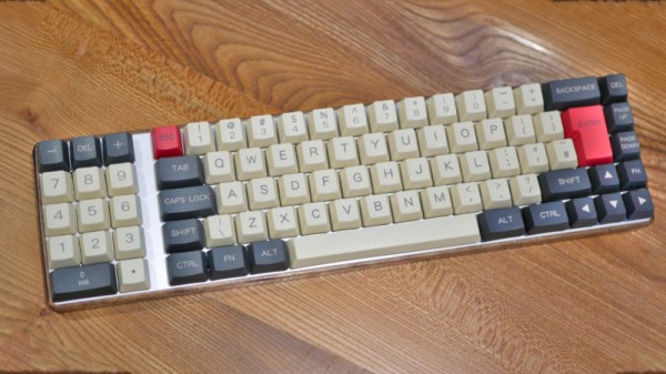
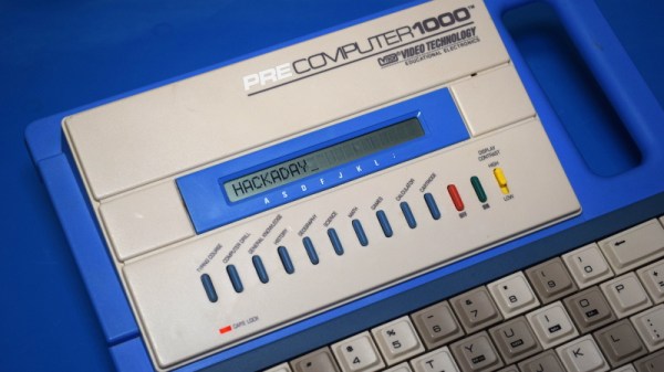
The VTech PreComputer 1000 is a perfect specimen of this particular style of educational toy. Released in 1988, it was advertised as a way for pre-teens to become more comfortable with operating a real computer; since at that point, it had become abundantly clear that the coming decade would see a beige box on every professional’s desk. Its full-size QWERTY keyboard was specifically mentioned in the product’s accompanying literature as a way to get young hands accustomed to the ways of touch typing.
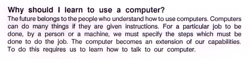
By the mid-1990s these devices would have progressed far enough to include passable text-to-speech capabilities and primitive graphics, but the junior professional who found him or herself seated in front of the PreComputer 1000 was treated to a far more spartan experience. It’s perhaps just as well that this particular educational computer was listed as a training tool, because even in 1988, surely a session with this toy must have felt very much like work.
But that’s not to say the PreComputer 1000 is without its own unique charms. In an effort to help cement its role as a “trainer” for more conventional computers, VTech saw fit to equip the PreComputer with its own BASIC interpreter. They even included generous written documentation that walked young programmers through the various commands and functions. Even today, there’s something oddly appealing about a mobile device with a full keyboard that can run BASIC programs for better than 24 hours on batteries (even if they’re alkaline “C” cells).
Let’s take a look inside this more than 30 year old mobile device, and see how the designers managed to create a reasonable facsimile of actual computing on a kid-friendly budget.