Homemade Magic Makes The Metcal Go

First soldering irons are often of the Radioshack or Maplin firestarter variety. They’re basically wall power shorted across a nichrome heater or similar with some inline resistance to make it harder to burn down the house. You plug them in, the current flows, and they get hot. Done.

If you stick with the hobby for a while, these eventually get replaced with something like the venerable HAKKO FX-888D or that one Weller everyone likes with the analog knob. These are much improved; having temperature control leads to a more consistently heated tip and much improved soldering experience.

Entering the electronics workplace one comes across the next level of quality soldering iron: high end HAKKOs, Metcals, JBCs, and the like. Using one of these irons is practically a religious experience; they heat in a flash and solder melts while you blink. They even turn off when you put the handpiece down! But they’re expensive to buy (hint: think used). What’s a hobbyist to do?

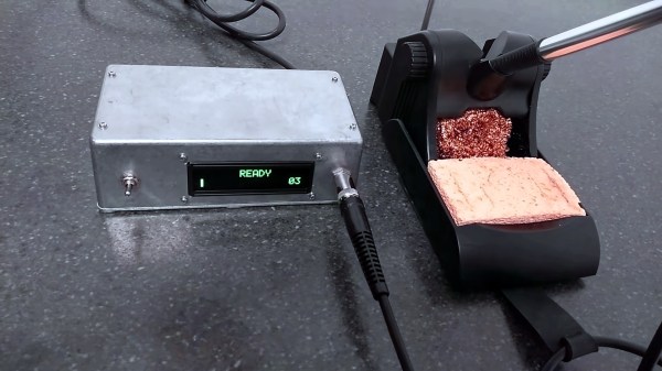
[SergeyMax] seems to have had this problem. He bit the bullet, figured out how the Metcal works, and made his own base. This is no mean feat as a Metcal might look like a regular iron but it’s significantly more complex than ye olde firestarter. The Metcal magic is based on a oscillating magnetic fields (notice the handpiece is connected via BNC?) interacting with a tip bearing a special coating. In the presence of the changing field the tip heats up until it hits its Curie temperature, at which point it stops interacting with the magnetic field and thus stops heating.

When the user solders, the tip cools by sinking its heat into the part and drops below the Curie temperature again, which starts the heating again. It’s like temperature control with the sensor placed absolutely as close to the part as possible and a nearly instant response time, without even a control loop! [SergeyMax] has a much more thorough description of how these irons work, which we definitely recommend reading.

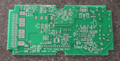
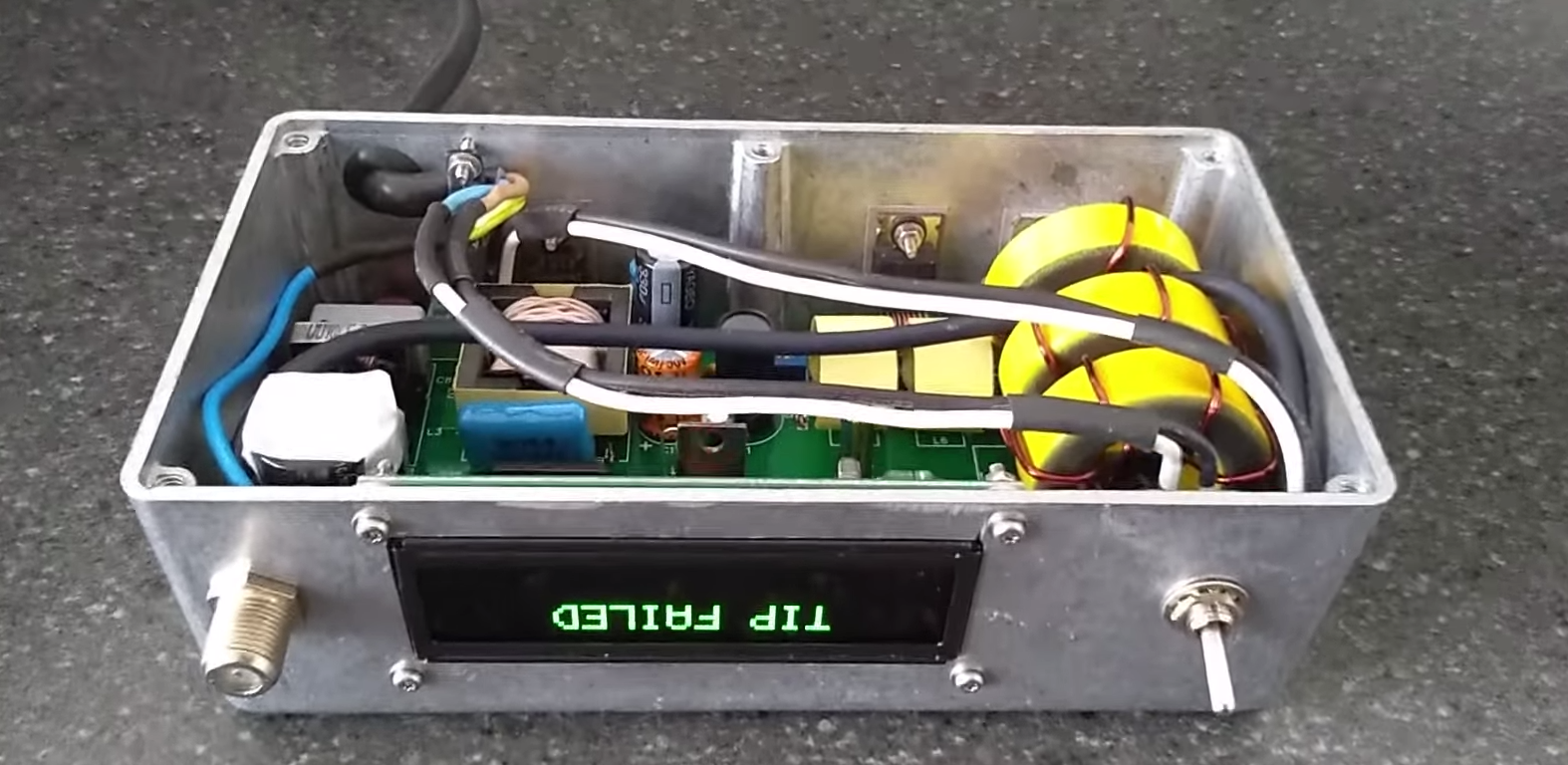
So what’s the hack? Based on old schematics and some clever reverse engineering from photos [SergeyMax] built a new base station! The published schematic is as rich with capacitors and inductors as one could hope. He didn’t post source or fab files but we suspect the schematic and photos of the bare board combined with some tinkering are enough for the enterprising hacker to replicate.

The post contains a very thorough description of the reverse engineering process and related concerns in designing a cost efficient version of the RF circuitry. Hopefully this isn’t the last Metcal replacement build we see! Video “walkthrough” after the break.

Edit: I may have missed it, but eagle eyed commentor [Florian Maunier] noticed that [SergeyMax] posted the sources to this hack on GitHub!

Continue reading “Homemade Magic Makes The Metcal Go”

Thrust Vectoring With Compliant Mechanisms Is Hard

Thrust vectoring is one way to control aerial vehicles. It’s become more popular as technology advances, finding applications on fifth-generation fighter aircraft, as well as long being used in space programmes the world over.[RCLifeOn] decided to try and bring the technology to a prop-powered RC aircraft, in an unconventional way.

After attending a lecture on compliant mechanisms and their potential use in space vehicles for thrust vectoring control, [RCLifeOn] decided to try applying the concept himself. His test mechanism is a fixed-wing with a single-piece motor mount that has enough flex in the right places to allow the motor (and propeller) to be moved in two axes, achieving thrust vectoring control.

After printing a compliant motor mount in a variety of materials, one was selected for having the right balance of strength and flexibility. The vectoring mechanism was fitted to a basic flying wing RC aircraft, and taken to the field for testing. Unfortunately, success was not the order of the day. While the mechanism was able to flex successfully and vector the motor in bench testing, it was unable to hold up to the stresses of powered flight. The compliant mechanism failed and the plane nosedived to the ground.

[RCLifeOn] suspects that the basic concept is a difficult proposition to engineer properly, as adding strength would tend to add weight which would make flight more difficult. Regardless, we’d love to see further development of the idea. It’s not the first time we’ve seen his 3D-printed flight experiments, either. Video after the break.

Continue reading “Thrust Vectoring With Compliant Mechanisms Is Hard”

Cycloid Drawing Machine Uses Sneaky Stepper Hack

Stepper motors are great for projects that require accurate control of motion. 3D printers, CNC machines and plotters are often built using these useful devices. [InventorArtist] built a stepper-based cycloid drawing machine, and made use of a nifty little hack along the way.

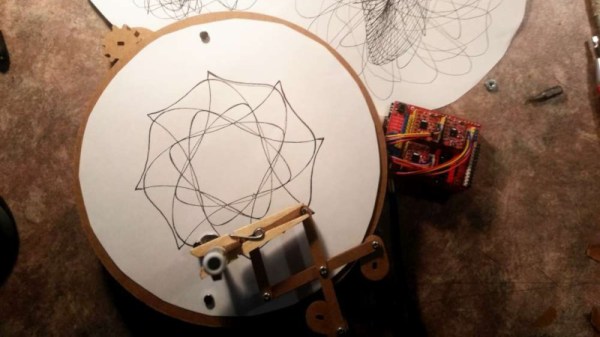
The machine uses a rotating turntable to spin a piece of drawing paper. A pen is then placed in a pantograph mechanism, controlled by another two stepper motors. The build uses the common 28BYJ-48 motor, which are a unipolar, 5-wire design. A common hack is to open these motors up and cut a trace in order to convert them to bipolar operation, netting more torque at the expense of being more complex to drive. [InventorArtist] worked in collaboration with [Doug Commons], who had the idea of instead simply drilling a hole through the case of the motor to cut the trace. This saves opening the motor, and makes the conversion a snap.

[InventorArtist] was able to create a machine capable of beautiful spirograph drawings, and develop a useful hack along the way. Reports are that a jig is in development to make the process foolproof for those keen to mod their own motors. We expect to see parts up on Thingiverse any day now. We’ve also covered the basic version of this hack before.

[Thanks to Darcy Whyte for the tip!]

The Smallest Hacker Camps Are The Most Satisfying, And You Can Do One Too

Two of my friends and I crammed into a small and aged European hatchback, drove all day along hundreds of miles of motorway, and finally through a succession of ever smaller roads. We were heading for a set of GPS co-ordinates in the north of Scotland, along with all of our camping gear.

There’s nothing like the hacker camp we’re looking for. After heading down a lane barely wider than the car, we drove through a farmyard with a sheepdog lying in the middle of the road (the reclining mutt seemed unconcerned as we edge the car around). We had arrived at GampGND, one of Europe’s smallest hacker camps.

Continue reading “The Smallest Hacker Camps Are The Most Satisfying, And You Can Do One Too”

Enforce Speed Limits With A Rusty Bike

They say you can’t manage what you can’t measure, and that certainly held true in the case of this bicycle that was used to measure the speed of cars in one Belgian neighborhood. If we understand the translation from Dutch correctly, the police were not enforcing the speed limit despite complaints. As a solution, the local citizenry built a bicycle with a radar gun that collected data which was then used to convince the police to enforce the speed limit on this road.

The bike isn’t the functional part of this build, as it doesn’t seem to have been intended to move. Rather, it was chosen because it is inconspicuous (read: rusty and not valuable) and simply housed the radar unit and electronics in a rear luggage case. The radar was specially calibrated to have less than 1% error, and ran on a deep cycle lead acid battery for around eight days. Fitting it with an Arduino-compatible shield and running some software (provided on the github page) is enough to get it up and running.

This is an impressive feat of citizen activism to provide the local police with accurate data to change a problem in a neighborhood. Not only was the technology put to good use, but the social engineering involved with hiding expensive electronics in plain sight with a rusty bicycle is a step beyond what we might have thought of as well.

Thanks to [Jo_elektro] for the tip!

Open Source Headset With Inside-Out Tracking, Video Passthrough

The folks behind the Atmos Extended Reality (XR) headset want to provide improved accessibility with an open ecosystem, and they aim to do it with a WebVR-capable headset design that is self-contained, 3D-printable, and open-sourced. Their immediate goal is to release a development kit, then refine the design for a wider release.

An early prototype of the open source Atmos Extended Reality headset.

The front of the headset has a camera-based tracking board to provide all the modern goodies like inside-out head and hand tracking as well as the ability to pass through video. The design also provides for a variety of interface methods such as eye tracking and 6 DoF controllers.

With all that, the headset gives users maximum flexibility to experiment with and create different applications while working to keep development simple. A short video showing off the modular design of the HMD and optical assembly is embedded below.

Extended Reality (XR) has emerged as a catch-all term to cover broad combinations of real and virtual elements. On one end of the spectrum are completely virtual elements such as in virtual reality (VR), and towards the other end of the spectrum are things like augmented reality (AR) in which virtual elements are integrated with real ones in varying ratios. With the ability to sense the real world and pass through video from the cameras, developers can choose to integrate as much or as little as they wish.

Terms like XR are a sign that the whole scene is still rapidly changing and it’s fascinating to see how development in this area is still within reach of small developers and individual hackers. The Atmos DK 1 developer kit aims to be released sometime in July, so anyone interested in getting in on the ground floor should read up on how to get involved with the project, which currently points people to their Twitter account (@atmosxr) and invites developers to their Discord server. You can also follow along on their newly published Hackaday.io page.

Continue reading “Open Source Headset With Inside-Out Tracking, Video Passthrough”

Try NopSCADlib For Your Next OpenSCAD Project

Most readers of this site are familiar by now with the OpenSCAD 3D modeling software, where you can write code to create 3D models. You may have even used OpenSCAD to output some STL files for your 3D printer. But for years now, [nophead] has been pushing OpenSCAD further than most, creating some complex utility and parts libraries to help with modeling, and a suite of Python scripts that generate printable STLs, laser-ready DXFs, bills of material, and human-readable assembly instructions complete with PNG imagery of exploded-view sub-assemblies.

Recently [nophead] tidied all of this OpenSCAD infrastructure up and released it on GitHub as NopSCADlib. You can find out more by browsing through the example projects and README file in the repository, and by reading the announcement blog post on the HydraRaptor blog. Some functionality highlights include:

  • a large parts library full of motors, buttons, smooth rod, et cetera
  • many utility functions to help with chamfers, fillets, precision holes, sub-assemblies, and BOM generation
  • Python scripts to automate the output of STLs, DXFs, and BOMs
  • automatic creation of documentation from Markdown embedded in your OpenSCAD files
  • automatic rendering of exploded subassemblies

All that’s missing is a nice Makefile to tie it all together! Try it out for your next project if you – like us – get giddy at the thought of putting your 3D projects into version control before “compiling” them into the real world.

We’ve discussed some complex OpenSCAD before: Mastering OpenSCAD Workflow, and An OpenSCAD Mini-ITX Computer Case.