Disassembling Mouse Sensors For Tracking Tongues

We just wrapped up the Human Computer Interface challenge in this year’s Hackaday Prize, and with that comes a bevy of interesting new designs for mice and keyboards that push the envelope of what you think should be possible, using components that seem improbable. One of the best examples of this is The Bit, a project from [oneohm]. It’s a computer mouse, that uses a tiny little trackpad in ways you never thought possible. It’s a mouse that fits on your tongue.

The idea behind The Bit was to create an input device for people with limited use of their extremities. It’s a bit like the Eyedriveomatic, the winner from the 2015 Hackaday Prize, but designed entirely to fit on the tip of your tongue.

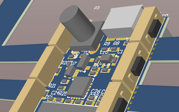
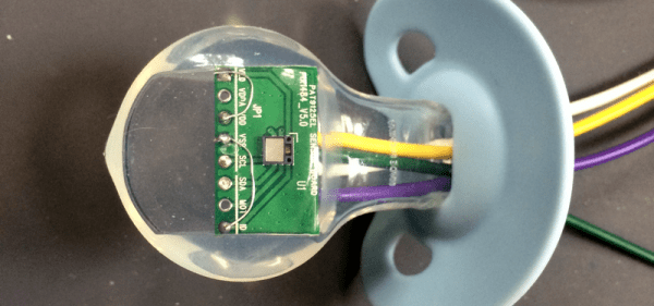
The first experiments on a tongue-controlled mouse were done with an optical trackpad/navigation button found on Blackberry Phones. Like all mouse sensors these days, these modules are actually tiny, really crappy cameras. [oneohm] picked up a pair of these modules and found they had completely different internal tracking modules, so the experiment turned to a surface tracking module from PixArt Imaging that’s also used as a filament sensor in the Prusa 3D printer. This module was easily connected to a microcontroller, and with careful application of plastics, was imbedded in a pacifier. Yes, it tracks a tongue and turns that into cursor movements. It’s a tongue-tracking mouse, and it works.

This is an awesome project for the Hackaday Prize. Not only does it bring new tech to a human-computer interface, it’s doing it in a way that’s accessible to all.

The Pre-CRT Oscilloscope

Oscilloscopes are especially magical because they translate the abstract world of electronics into something you can visualize. These days, a scope is likely to use an LCD or another kind of flat electronic display, but the gold standard for many years was the ubiquitous CRT (cathode ray tube). Historically, though, CRTs were not very common in the early days of electronics and radio. What we think of as a CRT didn’t really show up until 1931, although if you could draw a high vacuum and provide 30 kV, there were tubes as early as 1919. But there was a lot of electronics work done well before that, so how did early scientists visualize electric current? You might think the answer is “they didn’t,” but that’s not true. We are spoiled today with high-resolution electronic displays, but our grandfathers were clever and used what they had to visualize electronics.

Keep in mind, you couldn’t even get an electronic amplifier until the early 1900s (something we’ve talked about before). The earliest way to get a visual idea of what was happening in a circuit was purely a manual process. You would make measurements and draw your readings on a piece of graph paper.

Continue reading “The Pre-CRT Oscilloscope”

Northern Pike 3D printed plane

Awesome Looking 3D Printed RC Plane Is Full Of Design Considerations

Designing and 3D printing RC planes offer several interesting challenges, and so besides being awesome looking and a fast flier, [localfiend’s] Northern Pike build is definitely worth a look. Some details can be found by wading through this forum but there’s also quite a bit on his Thingiverse page.

Tongue-and-groove joint for the wing
Tongue-and-groove joint

Naturally, for an RC plane, weight is an issue. When’s the last time you used 0% infill, as he does for some parts? Those parts also have only one perimeter, making this thin-walled-construction indeed. He’s even cut out circles on the spars inside the wings. For extra strength, a cheap carbon fiber arrow from Walmart serves as a spar in the main wing section. Adding more strength yet, most parts go together with tongue-and-groove assembly, making for a stronger join than there would be otherwise. This slotted join also acts as a spar where it’s done for two wing sections. To handle higher temperatures, he recommends PETG, ABS, ASA, Polycarbonate, and nylon for the motor mount and firewall while the rest of the plane can be printed with PLA.

As you can tell from the videos below, [localfiend’s] flier is a high-performance 3D printed machine. But such machines don’t have to be relegated to the air as this RC jet boat demonstrates. Though some do hover on a thin cushion of air.

Continue reading “Awesome Looking 3D Printed RC Plane Is Full Of Design Considerations”

Do Space Probes Fail Because Of Space Weather?

Over the past few decades, numerous space probes sent to the far-flung reaches of the Solar System have fallen silent. These failures weren’t due to communications problems, probes flying into scientifically implausible anomalies, or little green men snatching up the robotic scouts we’ve sent out into the Solar System. No, these space probes have failed simply because engineers on Earth can’t point them. If you lose attitude control, you lose the ability to point a transmitter at Earth. If you’re managing a space telescope, losing the ability to point a spacecraft turns a valuable piece of scientific equipment into a worthless, spinning pile of junk.

The reasons for these failures is difficult to pin down, but now a few people have an idea. Failures of the Kepler, Dawn, Hayabusa, and FUSE space probes were due to failures of the reaction wheels in the spacecraft. These failures, in turn, were caused by space weather. Specifically, coronal mass ejections from the Sun. How did this research come about, and what does it mean for future missions to deep space?

Continue reading “Do Space Probes Fail Because Of Space Weather?”

How Big Is Your Oscilloscope? One Inch?

We are anxious to see the finished product of [Mark Omo’s] entry into our one square inch project. It is a 20 megasample per second oscilloscope that fits the form factor and includes a tiny OLED screen. We will confess that we started thinking if you could use these as replacements for panel meters or find some other excuse for it to exist. We finally realized, though, that it might not be very practical but it is undeniably cool.

There are some mockup PCB layouts, but the design appears feasible. A PIC32MZ provides the horsepower. [Mark] plans to use an interleaved mode in the chip’s converters to get 20 megasamples per second and a bandwidth of 10 MHz. It appears he’ll use DMA to drive the OLED. In addition to the OLED and the PIC, there’s a termination network and a variable gain stage and that’s about it.

Continue reading “How Big Is Your Oscilloscope? One Inch?”

Automagic Tool Makes KiCAD Schematic Symbols From PDFs

Last time we talked about a KiCAD tool it was to describe a way to make the zen-like task of manual assembly more convenient. But what about that most onerous of EE CAD tasks, part creation? Home makers probably don’t have access to expensive part library subscriptions or teams of people to create parts for them, so they are left to the tedium of creating them by hand. What if the dream tool existed that could read the darn PDF by itself and make a part? It turns out [Sébastien] made that tool and it’s called uConfig.

uConfig has a pretty simple premise. It scrapes manufacturer datasheets in PDF form, finds what it thinks are diagrams of parts with pin names, functions, etc, and emits the result as parts in a KiCAD library. To aid in the final conversion [Sébastien] added rules engine which consume his custom KiCAD Style Sheets which specify how to categorize pins. In the simple case the engine can string match or use regex to let you specify things like “all pins named VDD[A-C] should be power pins”. But it can also be used to move everything it thinks belongs to “GPIOB” and stick them on the bottom of the created symbol. We could imagine features like that would be of particular use breaking out gigantic parts like a 400 ball BeagleBone on a chip.

Thanks for the tip [arturo182]!

Better Than Original Pong Using Arduino

Games like Pong are legendary, not only in the sense that they are classic hours fun but also that they have a great potential for makers in stretching their learning legs. In an attempt at recreating the original paddle games like Pong and Tennis etc, [Grant Searle] has gone into the depths of emulating the AY-2-8500 chip using an Arduino.

For the uninitiated, the AY-3-8500 chip was the original game silicon that powered Ball & Paddle that could be played on the domestic television. Running at 2 MHz, it presented a 500 ns pixel width and operated to a maximum of 12 Volts. The equivalent of the AY-3-8500 is the TMS1965NLA manufactured by Texas Instruments for those who would be interested.

[Grant Searle] does a brilliant job of going into the details of the original chip as well as the PAL and NTSC versions of the device. This analysis will come in handy should anyone choose to make a better version. He talks about the intricacies of redrawing the screen for the static elements as well as the ball that bounces around the screen. The author presents details on ball traversal, resolution, 2K memory limit and its workarounds.

Then there are details on the sound and the breadboard version of the prototype that makes the whole write-up worth one’s time. If you don’t fancy the analog paddles and would rather use a wireless modern-day touch, check out Playing Pong with Micro:bits

Thanks [Keith O] for the tip.