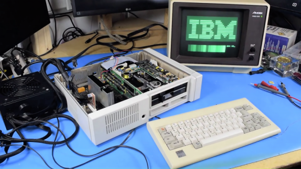
The IBM PCjr was a computer only the marketing geniuses of a multi-billion dollar corporation could love. On the face of it, it seemed like a great idea – a machine for the home market, meant to complement the “big boy” IBM PC in the office and compete against the likes of Apple and Commodore. What it ended up as was a universally hated, only partially PC-compatible machine which sold a mere half-million units before being mercifully killed off.
That doesn’t mean retrocomputing fans don’t still snap up the remaining machines, of course. [AkBKukU] scored a PCjr from a thrift store, but without the original external brick power supply. An eBay replacement for the 18-VAC supply would have cost more than the computer, so [AkBKukU] adapted a standard ATX power supply to run the PCjr. It looked as if it would be an easy job, since the external brick plugs into a power supply card inside the case which slots into the motherboard with a card-edge connector. Just etch up a PCB, solder on an ATX Molex connector, and plug it in, right? Well, not quite. The comedy of errors that ensued, from the backward PCB to the mysteriously conductive flux, nearly landed this one in the “Fail of the Week” bin. But [AkBKukU] soldiered on, and his hand-scratched adapter eventually prevailed; the video below tells the whole sordid tale, which thankfully ended with the sound of the machine booting from the 5-1/4″-floppy drive.
In the end, we’ve got to applaud [AkBKukU] for taking on the care and feeding of a machine so unloved as to be mentioned only a handful of times even on these pages. One of those articles marks the 25th anniversary of the PCjr, and lays out some of the reasons for its rapid disappearance from the market.
Continue reading “IBM PCjr Revived By An ATX Power Supply And Many False Starts”
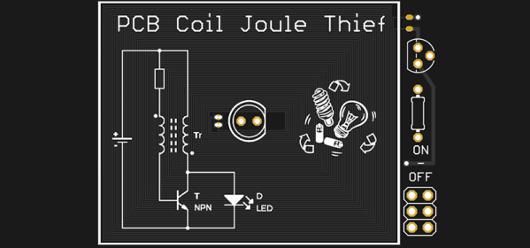
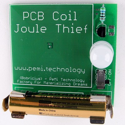 At the forefront of these experiments in PCB coil design is [bobricious], and already he’s made brushless and linear motors using only tiny copper traces on top of fiberglass. Now he’s experimenting with inductors. His latest entry to the Hackaday Prize


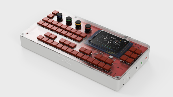
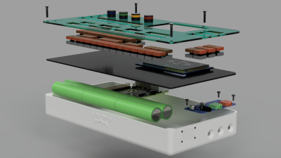 On the hardware side, the heart of the OTTO is a Raspberry Pi 3. The all-important audio interface is a Fe-Pi Audio Z V2, though a USB interface can be used. The 48 switches and four rotary encoders are wrangled by a pair of Arduino pro micros which pass the data on to the Pi. Data is related to the user through a 320×200 LCD.
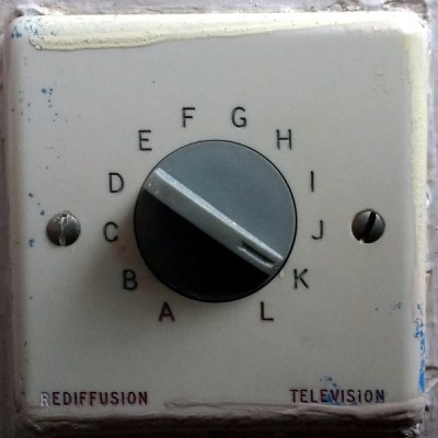 Housed on a standard-sized British electrical fascia was a 12-position rotary switch, marked with letters A through L. An unexpected thing to see in the 21st century and one probably unfamiliar to most people under about 40, I’d found something I’d not seen since my university days in the early 1990s: a Rediffusion selector switch.