Have you ever been seduced by a claw machine in an arcade, only to have your hopes of a cuddly toy dashed as it fails to hang onto your choice? Then you’re in luck, because now you can play to your heart’s content online. [Ryan Walmsley] wants you to control his Raspberry Pi-driven claw machine.
Hardware-wise he’s replaced the original 8052 microcontroller and relay control with the Pi and a custom H-bridge PCB. We particularly light the warning: “Highish voltage”, and we feel it should appear more often. There is some code in his GitHub repository, but we suspect it doesn’t have everything.
We had a lot of fun digging into the documentation on this one. From his initial thoughts through some prototyping and a board failure, to the launch of the online version and finally a run-down of how it all works, he’s got it covered.
Sadly the machine itself isn’t online all the time, it seems to be only online when [Ryan] is at home, so if you live on the other side of the world from his British base you may be out of luck. Fortunately though his previous live streams are online, so you can see it in action on a past outing below the break.
Of course what kind of swag do you load up in a claw machine like this one? On his Twitter feed we’ve seen tests of the aliens from Toy Story (who start their existence in a claw machine so quite fitting). The majority of items show in is recorded games — now numbering over 2000 — have been our beloved companion cube.


 Where this really stands out is that
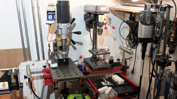
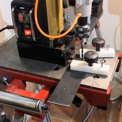 For the non-metalworkers out there, a mag-base drill is basically a portable drill press where the base is replaced with a strong electromagnet like the one shown here. They’re often used in the construction trades to drill holes in steel beams or columns, and often include nice features like a built-in coolant system.