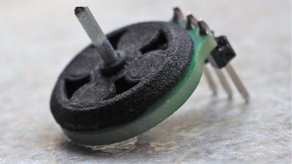
Piezomagnetic Trick Shrinks 2.5 GHz Antennas

To a ham radio operator used to “short”-wave antennas with lengths listed in tens of meters, the tiny antennas used in the gigahertz bands barely even register. But if your goal is making radio electronics that’s small enough to swallow, an antenna of a few centimeters is too big. Physics determines plausible antenna sizes, and there’s no way around that, but a large group of researchers and engineers have found a way of side-stepping the problem: resonating a nano-antenna acoustically instead of electromagnetically.

Normal antennas are tuned to some extent to the frequency that you want to pick up. Since the wavelength of a 2.5 GHz electromagnetic wave in free space is 120 cm mm, most practical antennas need a wire in the 12-60 cm mm range to bounce signals back and forth. The trick in the paper is to use a special piezomagnetic material as the antenna. Incoming radio waves get quickly turned into acoustic waves — physical movement in the nano-crystals. Since these sound waves travel a lot slower than the speed of light, they resonate off the walls of the crystal over a much shorter distance. A piezoelectric film layer turns these vibrations back into electrical signals.

Ceramic chip antennas use a similar trick. There, electromagnetic waves are slowed down inside the high-permittivity ceramic. But chip antennas are just slowing down EM waves, whereas the research demonstrated here is converting the EM to sound waves, which travel many orders of magnitude slower. Nice trick.

Granted, significant material science derring-do makes this possible, and you’re not going to be fabricating your own nanoscale piezomagnetic antennas any time soon, but with everything but the antenna getting nano-ified, it’s exciting to think of a future where the antennas can be baked directly into the IC.

Thanks [Ostracus] for the tip in the comments of this post on antenna basics. Via [Science Magazine].

The 1980s Called – Asking For The Z80 Membership Card

The ’80’s and early ’90’s saw a huge proliferation of “personal” computers, spawning an army of hacker kids who would go on to hone their computing chops on 8-bit and 16-bit computers from brands such as Sinclair, Commodore, Acorn, Apple, Atari, Tandy/RadioShack and Texas Instruments. Fast forward to 2017, and Raspberry-Pi, BeagleBone and micro:bit computers reign supreme. But the old 8-bit and 16-bit computer systems can still teach us a lot.

[Lee Hart] has built the amazing Z80 Membership Card — a Z80 computer that fits in an Altoids tin. His design uses generic through hole parts mounted on a PCB with large pads, thick tracks and lots of track clearances, making assembly easy. Add to this his detailed documentation, where he weaves some amazing story telling, and it makes for a really enjoyable, nostalgic build. It makes you want to get under the hood and learn about computers all over again. The Z80 Membership Card features a Zilog Z80 microprocessor running at 4 MHz with 32k RAM and 32K EPROM, loaded with BASIC interpreter and monitor programs. A pair of 30-pin headers provide connections to power, I/O pins, data, address and control signals.

To accompany this board, he’s built a couple of companion “shield” boards. The Front Panel Card has a 16-key hex pad, 7-digit 7-segment LED display and Serial port. [Lee] has packed in a ton of features on the custom monitor ROM for the front panel card making it a versatile, two board, 8-bit system. Recently, he finished testing a third board in this series — a Serial/SD-Card/RAM shield which adds bank-switchable RAM and SD-card interface to provide “disk” storage. He’s managed to run a full CP/M-80 operating system on it using 64k of RAM. The two-board stack fits nicely in a regular Altoids tin. A fellow hacker who built the three-board sandwich found it too tall for the Altoids tin, and shared the design for a 3D printable enclosure.

[Lee] provides detailed documentation about the project on his blog with schematics, assembly instructions and code. He’s happy to answer questions from anyone who wants help building this computer. Do check out all of his other projects, a couple of which we’ve covered in the past. Check out Lee Hart’s Membership Card — a similar Altoids tin sized tribute to the 1802 CMOS chip and how he’s Anthropomorphizing Microprocessors.

Finally, we have to stress this once again — check out his Assembly Manuals [PDF, exhibit #1] — they are amazingly entertaining.

Thanks to [Matthew Kelley] who grabbed one of [Lee]’s kits and then tipped us off.

Tesla Coil Uses Vintage Tube

We’ve seen a fair amount of Tesla coil builds, but ones using vacuum tubes are few and far between. Maybe it’s the lack of availability of high power tubes, or a lack of experience working with them among the younger crop of hackers. [Radu Motisan] built a vacuum tube Tesla coil several years back, and only just managed to tip us off recently. Considering it was his first rodeo with vacuum tubes, he seems to have done pretty well — not only did he get good results, he also managed to learn a lot in the process.

His design is based around a GI-30 medium power dual tetrode. The circuit is a classical Armstrong oscillator with very few parts and ought to be easy to build if you can lay your hands on the tricky parts. The high voltage capacitors may need some scrounging. And of course, one needs to hand-wind the three coils that make up the output transformer.

Getting the turns ratios of the coils right is quite critical in obtaining proper power transfer to the output. This required a fair amount of trial error before [Radu] could get it right.

The use of a 20W fluorescent tubelight ballast to limit the inrush current is a pretty nice idea to prevent nuisance tripping of the breakers. If you’d like to try making one of your own, head over to his blog post where you will find pictures documenting his build in detail. If you do decide to make one, be extremely careful — this circuit has lethal high voltages in addition to the obvious ones, since it operates directly from 220 V utility supply.

Continue reading “Tesla Coil Uses Vintage Tube”

Winch Bot Records Hacks And Cats

Some people are better than others when it comes to documenting their hacks. Some people, like [Micah Elizabeth Scott], aka [scanlime], set the gold standard with their recordings. Hacking sessions with the Winch Bot have been streamed regularly throughout the build and this is going to lead to a stacking effect in her next projects because the Winch Bot was designed to record hacking sessions. Hacking video inception anyone? Her Winch Bot summary video is after the break.

The first part of this build, which she calls the Tuco Flyer, was [Micah Elizabeth Scott]’s camera gimbal hack which we already covered and is a wonderful learning experience in itself. She refers to the gimbal portion as the “flyer” since it can move around. The Winch Bot contains the stationary parts of the Tuco Flyer and control where the camera will be in the room.

Continue reading “Winch Bot Records Hacks And Cats”

Remote Controlled Streaming Speakers

For want of a better use of a spare Raspberry Pi Zero W and a set of LogitechZ-680 surround sound speakers, [Andre van Kammen] hacked them together to make them stream music playing from his phone.

It was stumbling across the Pi Music Box distribution that really got the ball rolling, and the purchase of a pHAT DAC laid the foundation. Cracking open the speakers’ controller case, [Kammen] was able to get 5V of power off some terminals even when the speakers were on standby — awesome! — which the Pi could use. Power and volume are controlled via the Pi’s GPIO pins with a diode to drop the voltage and prevent shorts.

Now, how to tell whether the speakers are on or off? Well, a pin on the display connector changes to 4.3V when it’s on, so wiring a 10k resistor and a diode to said pin is a hackable solution. Finishing off the wired connections, it proved possible to cram the pHAT DAC inside the controller case with the GPIO header sticking out the back to mount the Pi upon with no other external wires — double awesome!

Continue reading “Remote Controlled Streaming Speakers”

Battery Management Module Hacked For Lithium-Iron Battery Bank

In a departure from his usual repair and tear down fare, [Kerry Wong] has set out on a long-term project — building a whole-house battery bank. From the first look at the project, this will be one to watch.

To be fair, [Kerry] gave us a tease at this project a few months back with his DIY spot welder for battery tabs. Since then, he appears to have made a few crucial design decisions, not least of which is battery chemistry. Most battery banks designed for an inverter with enough power to run household appliances rely on lead-acid batteries, although lithium-ion has certainly made some inroads. [Kerry] is looking to run a fairly small 1000-watt inverter, and his analysis led him to lithium-iron cells. The video below shows what happens when an eBay pack of 80 32650 LiFePo4 cells meets his spot welder. But then the problem becomes one of sourcing a battery management system that’s up to the charge and discharge specs of his 4s battery pack. We won’t spoil the surprise for you, but suffice it to say that [Kerry] really lucked out that only minimal modifications were needed for his $9 off-the-shelf BMS module.

We’re looking forward to seeing where this build goes, not least because we’d like to build something similar too. For a more traditional AGM-based battery bank, check out this nicely-engineered solar-charged system.

Continue reading “Battery Management Module Hacked For Lithium-Iron Battery Bank”

Hackaday Prize Entry: An Optical Power Meter

This is the type of crowd that’s famous for building their own test equipment. If you need a way to program a flash chip, don’t go out and buy one — you can just build one. Need a spectrum analyzer? You can build that out of copper clad board. For his Hackaday Prize entry, [oakkar7] is building an optical power meter, capable enough to do futzy fiber work, but still completely DIY.

When you get into networking and telecom connections that don’t begin with the letters ‘RJ’, you start to stumble upon SPF transceivers. These ‘small form factor pluggable’ devices are little modular transceivers capable of handling fiber, Gigabit Ethernet, and other slightly weirder bit pipes. When used with fiber, they can measure optical power in dBm and watts, and can be debugged by a UART.

[oakkar]’s optical power meter uses these SPF transceivers, tied together with a fairly simple circuit consisting of an Arduino, a few tact switches, a Nokia LCD, and an FTDI UART. The key in tying all of this together is an Arduino library for SPF and DDM (Digital Diagnostics Monitoring), giving the user access to all the configuration bits in these transceivers.

While the circuit is simple enough to be built on a piece of perfboard, [oakkar] really knocked it out of the park with the enclosure on this one. With just a little bit of laser cut acrylic and a few standoffs, [oakkar] has a device that actually looks professional, and has most of the capabilities of fancier, more expensive tools.