NextThingCo Introduces C.H.I.P. Pro, GR8 System On Module

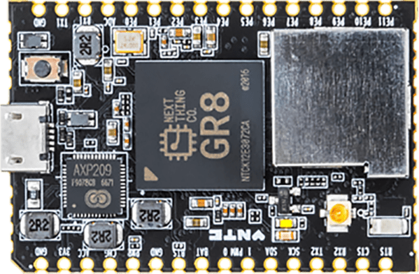
NextThingCo, makers of the very popular C.H.I.P. single board Linux computer, have released the latest iteration of their hardware. It’s the C.H.I.P. Pro, an SBC designed to be the embedded brains of your next great project, product, or Internet of Things thing.

The C.H.I.P. Pro features an Allwinner R8 ARMv7 Cortex-A8 running at 1 GHz, a MALI-400 GPU, and either 256 MB or 512 MB of NAND Flash. The Pro also features 802.11 b/g/n WiFi, Bluetooth 4.2, and is fully certified by the FCC. This board will be available in December at supposedly any quantity for $16.

The design of the C.H.I.P. Pro is a mix between a module designed to be installed in a product and a single board computer designed for a breadboard. It features castellated edges like hundreds of other modules, but the design means that assembly won’t be as simple as throwing down some paste and reflowing everything. The C.H.I.P. Pro features parts on two sides, making reflow questionable and either 0.1″ headers or a cutout on a PCB necessary. As a single board computer, this thing is small, powerful, and a worthy competitor to the Raspberry Pi Zero. A C.H.I.P. Pro development kit, consisting of two C.H.I.P. Pro units, a ‘debug’ board, and headers for breadboarding, is available for $49, with an estimated ship date in December.

A $16 Linux module with WiFi, Bluetooth, and no NDA is neat, but perhaps a more interesting announcement is that NextThingCo will also be selling the module that powers the C.H.I.P. Pro.

The GR8 module includes an Allwinner R8 ARMv7 Cortex-A8 running at 1 GHz, a MALI-400 GPU, and 256 MB of DDR3 SDRAM. Peripherals include TWI, two UARTS, SPI (SD cards support is hacked onto this), two PWM outputs, a single 6-bit ADC, I2S audio, S/PDIF, one USB 2.0 Host and one USB 2.0 OTG, and a parallel camera interface. This isn’t really a chip meant for video out, but it does support TV out and a parallel LCD interface. A limited datasheet for the GR8 is available on the NextThingCo GitHub.

Putting an entire Linux system on a single BGA module must draw comparisons to the recent release of the Octavo Systems OSD355X family, best known to the Hackaday audiences as the Beaglebone on a chip. Mechanically, the Octavo chip will be a bit easier to solder. Even though it has almost twice as many balls as the GR8, 400 on the Octavo and 252 on the GR8, the Octavo has a much wider pitch between the balls, making escape routing much easier.

Comparing peripherals between the OSD355X and GR8, it’s a bit of a wash, with the OSD coming out slightly ahead with Ethernet, more RAM and fancy TI PRUs. Concerning pricing, the GR8 wins hands down at $6 per chip in any quantity. That’s significantly less than the OSD355X.

The original C.H.I.P. has been exceptionally well received by the community NextThingCo is marketing to, despite the community’s distaste for Allwinner CPUs, cringeworthy PR, and questions concerning the true price of the C.H.I.P.. The C.H.I.P. Pro will surely see more than a few uses, but the GR8 is the real story here. A jellybean part that contains an entire Linux system has been the fevered dream of a madman for years now. The GR8 makes putting the power of open software into any project much easier, and we can’t wait to see the applications it allows.

Hackaday Prize Entry: Hands|On Gloves Speaks Sign Language

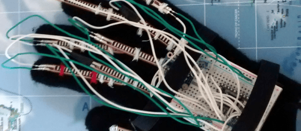
The Hands|On glove looks like it’s a PowerGlove replacement, but it’s a lot more and a lot better. (Which is not to say that the Power Glove wasn’t cool. It was bad.) And it has to be — the task that it’s tackling isn’t playing stripped-down video games, but instead reading out loud the user’s sign-language gestures so that people who don’t understand sign can understand those who do.

The glove needs a lot of sensor data to accurately interpret the user’s gestures, and the Hands|On doesn’t disappoint. Multiple flex sensors are attached to each finger, so that the glove can tell which joints are bent. Some fingers have capacitive touch pads on them so that the glove can know when two fingers are touching each other, which is important in the US sign alphabet. Finally, the glove has a nine degree-of-freedom inertial measurement unit (IMU) so that it can keep track of pitch, yaw, and roll as well as the hand’s orientation.

In short, the glove takes in a lot of data. This data is cleaned up and analyzed in a Teensy 3.2 board, and sent off over Bluetooth to its final destination. There’s a lot of work done (and some still to be done) on the software side as well. Have a read through the project’s report (PDF) if you’re interested in support vector machines for sign classification.

Sign language is most deaf folks’ native language, and it’s a shame that the hearing community can’t understand it directly. Breaking down that barrier is a great idea, and it makes a great entry in the Hackaday Prize!

Resurrecting The Retro-futuristic Poly-1

poly1clean

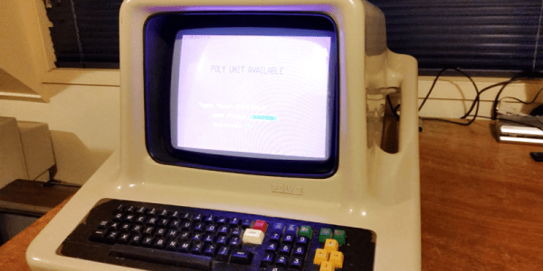
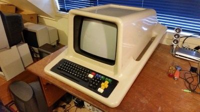
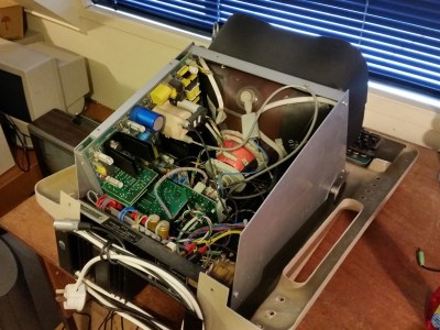
[Tez] has acquired and resurrected a piece of New Zealand computing history, the Poly-1. To anyone who went to school in 1980s Britain, the Poly-1 appears to be a cooler, mirror universe version of Acorn’s BBC Micro. Like the humble Beeb, the Poly-1 was designed primarily for educational use. It also used a related, but superior, microprocessor (the Motorola 6809).

However while the legacy of Acorn lives on in the ARM architecture, only a few thousand Poly-1s were ever sold and it appears to have been largely forgotten.

poly1inards

The Poly-1’s demise was likely in part due to its high price tag — around $5,000 USD — its lack of support within New Zealand, and the difficulty that the small New Zealand company had breaking into international markets: issues which eventually killed off many similar 1980s computer companies in the UK, Japan and elsewhere.

But it’s still fascinating to look back, not just in nostalgia, but in admiration of the intrepid 1980s hackers who created these beautiful machines and the dream of a world that might have been.

3D Printed Electric Longboard Courtesy Of Stratasys

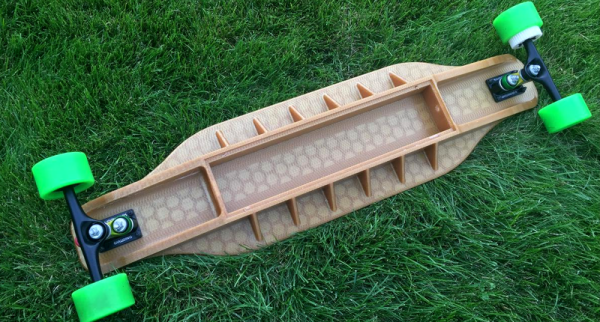
[Tallaustin] worked at Stratasys as an intern this past summer. They let him know that he was welcome to use their fancy industrial printers as much as he’d like. Not to waste such an opportunity he promptly got to work and designed an electric longboard, printable for a mere $8,000.

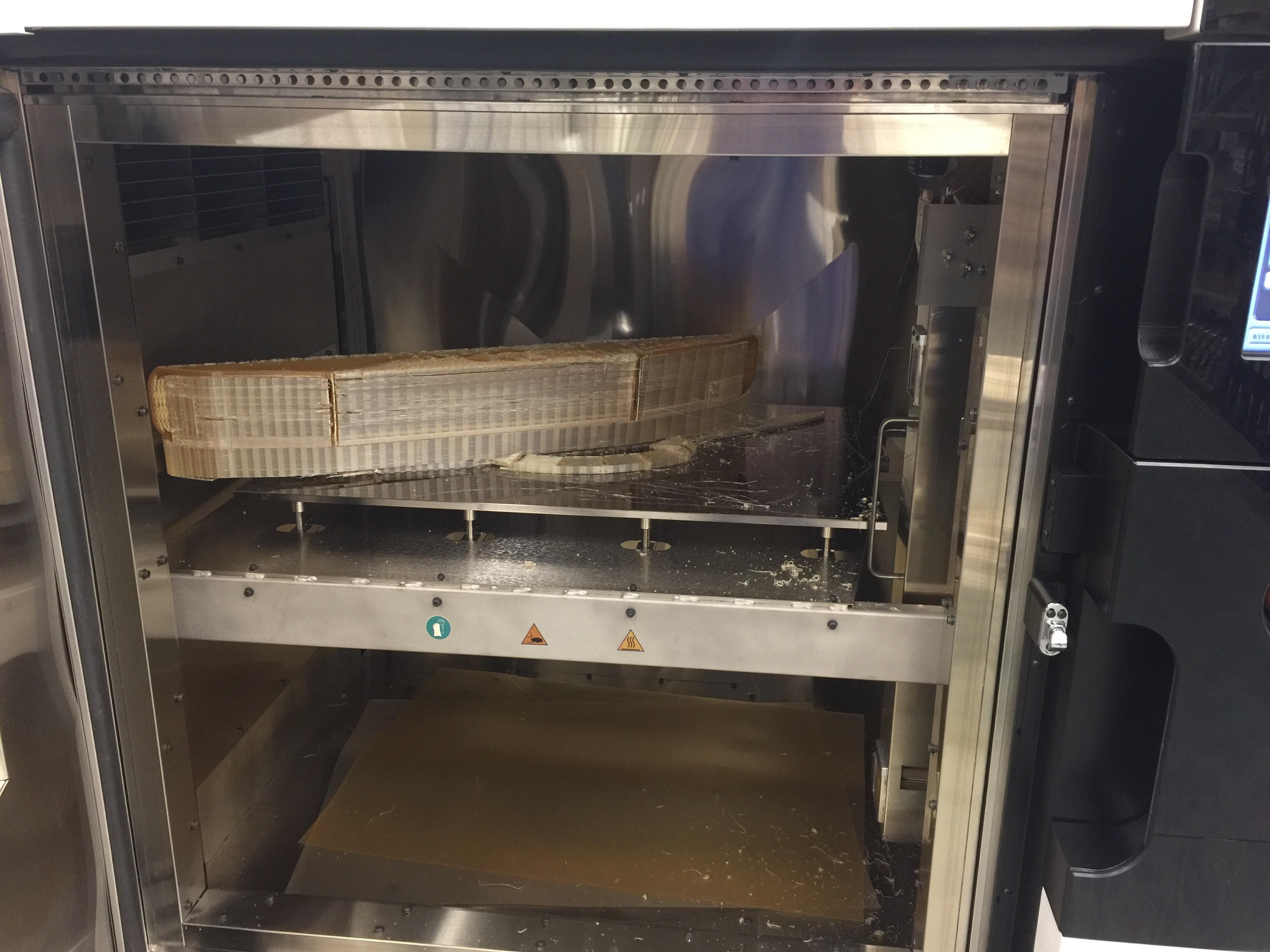
Just in case the idea of a 3D printer that can print a whole longboard was causing envy. Here's a photo of a print delaminating inside of it half way. Just in case the idea of a 3D printer that can print a whole longboard was causing envy. Here's a photo of a print delaminating inside of it half way.
Just in case the idea of a 3D printer that can print a whole longboard was inducing acute envy. Here’s a photo of a print delaminating inside of it half way through.

[Tallaustin] is presumably tall, and confided to Reddit that he weighs in at 210 lbs. For those of us who have had the pleasure of designing for FDM 3D printing, we know that getting a skateboard one can actually skate on without it delaminating somewhere unexpected is pretty difficult if you weigh 80 lbs, 200+  is another category entirely. So it’s not surprising that his first version shattered within in moments of testing.

So, he went back to the drawing board. Since he had his pick of all of Stratasys’s most expensive and fine spools of plastic, he picked one of the expensivest and finest, Ultem 1010. Aside from adding a lot of ribbing and plastic, he also gave it a full rundown with some of SolidWorks’s simulation tools to see if there were any obvious weak points.

Six days of exceedingly expensive printing later, he had a working long board. The base holds some batteries, an ESC, and a 2.4 GHz transceiver. The back has a brushless motor that drives a pulley slotted into one of the wheels. The rest is standard skateboard hardware.

If you’d like to build it yourself he’s posted the design on Thingiverse. He was even nice enough to put together a version that’s printable on a plebeian printer, for a hundredth of the price.

Blooming Flower Lamp Will Test Your 3D Printer

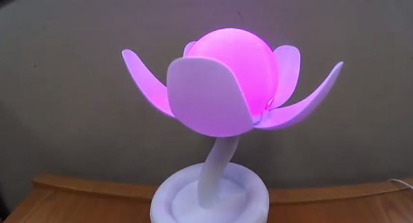
[ossum] has a baby on the way. He admits that he got a bit carried away, brimming with parental excitement. What resulted is a fully articulated LED WiFi lamp that blooms and glows dramatically in the friendly confines of the oncoming baby’s room.

We’ve covered [ossum]’s work before. As usual, he started off by showing his complete mastery of Fusion360 and making the rest of us look bad. If you want to learn 360, we recommend scrobbing through his models to see how it’s done.  The base encloses an ESP8266 and a hobby servo. A clever mechanism pulls down on a stranded steel cable that runs through the stem along with some control lines for the LEDS. This opens and closes the petals. The LEDs are all held in a 3D printed frame which produces a nice even glow.

If you’d like to build one yourself, there’s a full video viewable after the break. Files are available on Thingiverse. Just make sure you tune up your printer first, this is a tough one.

Continue reading “Blooming Flower Lamp Will Test Your 3D Printer”

64×16 LED MQTT Laundry Display

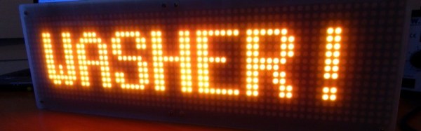
When you have an MQTT broker receiving messages, you want to be able to see them. [Xose Pérez] already had a system set up that sent him notifications, but he had a pair of 32×16 LED matrices, so he decided to make a big, bright sign to let him know when he got an important message sent to the broker.

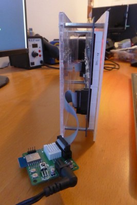
[Xose Pérez] had already built a laundry monitor which was sending messages to an MQTT broker so he wouldn’t forget his laundry sitting in the washing machine. To communicate with the broker, he used an ESP-12. He had already ported an Arduino library for the Holtek HT1362C display drivers used by the matrices to work with his driver board.

mqtt-led-matrix-driver-boardHe wanted to try out SMD soldering so he built a custom PCB to hold the ESP-12, power supply, passive components, and a connector and he describes his methods and results. Instead of hardcoded messages, he wanted the system to be configurable and display messages coming in, not only from his laundry system, but also from other sensors. A web interface, built with jQuery and WebSockets, running on the ESP-12 allows the user to subscribe to a topic on the broker and show a customized name and value on the display when a payload is available.

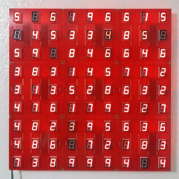
All-in-all, [Xose Pérez] has posted a great tutorial in which he goes over the hardware he built, the libraries he used, SMD soldering, how he made the enclosure, and even his choice in IDE (PlatformIO). He also posted the software, board designs and enclosure models software and hardware on bitbucket. The end result is a great looking LED matrix that displays not only his laundry’s status, but also anything else he wants to from his MQTT broker.

If you want to try your hand with MQTT, the ESP8266 is a wonderful device for sensor nodes, and any Linux box (like the Raspberry Pi) makes an easy broker. Check out [Elliot Williams’] Minimal MQTT series and you will be up and running in no time.

Creating A PCB In Everything: Friends Don’t Let Friends Use Fritzing

This week, we’re continuing our Creating A PCB In Everything series, where we go through the steps to create a simple, barebones PCB in different EDA suites. We’re done with Eagle, and now it’s time to move onto Fritzing.

fritzing-logoFritzing came out of the Interaction Design Lab at the University of Applied Sciences of Potsdam in 2007 as a project initiated by Professor Reto Wettach, André Knörig and Zach Eveland. It is frequently compared to Processing, Wiring, or Arduino in that it provides an easy way for artists, creatives, or ‘makers’ to dip their toes into the waters of PCB design.

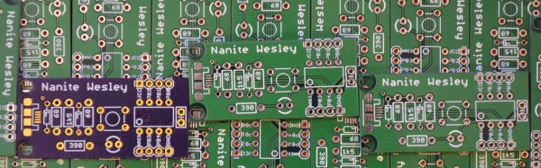
I feel it is necessary to contextualize Fritzing in the space of ‘maker movement’, DIY electronics, and the last decade of Hackaday. Simply by virtue of being an editor for Hackaday, I have seen thousands of homebrew PCBs, and tens of thousands of amateur and hobbyist electronics projects. Despite what the Fritzing’s Wikipedia talk page claims, Fritzing is an important piece of software. The story of the ‘maker movement’ – however ill-defined that phrase is – cannot be told without mentioning Fritzing. It was the inspiration for CircuitLab, and the Fritzing influence can easily be seen in Autodesk’s 123D Circuits.

Just because a piece of software is important doesn’t mean it’s good. I am, perhaps, the world’s leading expert at assessing poorly designed and just plain shitty PCBs. You may scoff at this, but think about it: simply due to my vocation, I look at a lot of PCBs made by amateurs. EE professors, TAs, or Chris Gammell might beat me on volume, but they’re only looking at boards made by students using one tool. I see amateur boards built in every tool, and without exception, the worst are always designed in Fritzing. It should be unacceptable that I can even tell they’re designed in Fritzing.

Fritzing has its place, and that place is building graphical representations for breadboard circuits. Fritzing has no other equal in this respect, and for this purpose, it’s an excellent tool. You can also make a PCB in Fritzing, and here things aren’t as great. I want to do Fritzing for this Creating A PCB In Everything series only to demonstrate how bad PCB design can be.

For the next few thousand words, I am going to combine a tutorial for Fritzing with a review of Fritzing. Fritzing is an important piece of software, if only for being a great way to create graphics of breadboard circuits. As a PCB design tool, it’s lacking; creating parts from scratch is far too hard, and there’s no way to get around the grid snap tool. No one should ever be forced to create a PCB in Fritzing, but it does have its own very limited place.

Continue reading “Creating A PCB In Everything: Friends Don’t Let Friends Use Fritzing”