Launchpad Takes Ultra Low Power To The Extreme

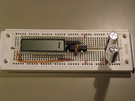
We’ve all known the MSP430s under the Launchpad are designed to be low power, but who wants to bet how long the chip can last on only 20F worth of capacitors? A couple of hours? A day at max? [Kenneth Finnegan] setup a MSP430 with supercaps to find out. To make sure the chip is actually running, [Kenneth] programmed it to count from 0 to 9 over a period of 10 seconds, and then reset. To get it ultra low power, the chip is in sleep mode most of the time, and a raw low current LCD is used to display the output. While [Kenneth] simply checks the chip every few hours to see if it’s still counting, a setup much like the Flash Destroyer, tracking a clock and then storing the current value would get a more exact time of death. Either way, it’s been over 3 weeks…and still counting. Video after the rift.

Continue reading “Launchpad Takes Ultra Low Power To The Extreme”

A Simple Hack For Running Low-Power Gear From A USB Battery Pack

We’ve all been there. You’ve cooked up some little microcontroller project, but you need to unhook it from your dev PC and go mobile. There’s just one problem — you haven’t worked up a battery solution yet. “No problem!” you exclaim. “I’ll just use a USB battery pack!” But the current draw is too low, and the pack won’t stay on. “Blast!” you exclaim, because you’ve been watching too much Family Guy or something.

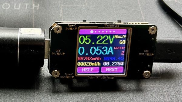
[PatH] had this very problem recently, when trying to work with Meshtastic running on a RAKwireless WisBlock Base Board. You’re supposed to hook up your own rechargeable LiPo battery, but [PatH] was in a hurry. Instead, a USB battery pack was pressed into service, but it kept shutting down. The simple trick was to just add a 100-ohm resistor across the device’s battery terminals. That took the current draw from just 15 mA up to 53 mA, which was enough to keep portable USB power banks interested in staying switched on.

It’s an easy hack for an oddball problem, and it just might get you out of a bind one day. If you’ve got any nifty tricks like this up your sleeve, don’t hesitate to let us know!

A Compact SMD Reflow Hotplate Powered By USB-PD

When it comes to home-lab reflow work, there are a lot of ways to get the job done. The easiest thing to do perhaps is to slap a PID controller on an old toaster oven and call it a day. But if your bench space is limited, you might want to put this compact reflow hotplate to work for you.

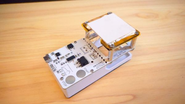
There are a lot of nice features in [Toby Chui]’s build, not least of which is the heating element. Many DIY reflow hotplates use a PCB heater, where long, thin traces in the board are used as resistive heating elements. This seems like a great idea, but as [Toby] explains in the project video below, even high-temperature FR4 substrate isn’t rated for the kinds of temperatures needed for some reflow profiles. His search for alternatives led him to metal ceramic heaters (MCH), which are commonly found in medical and laboratory applications. The MCH he chose was rated for 20 VDC at 50 watts — perfect for powering with USB-PD.

The heater sits above the main PCB on a Kapton-wrapped MDF frame with a thermistor to close the loop. While it’s not the biggest work surface we’ve seen, it’s a good size for small projects. The microcontroller is a CH552, which we’ve talked about before; aside from that and the IP2721 PD trigger chip needed to get the full 60 watts out of the USB-PD supply, there’s not much else on the main board.

This looks like a nice design, and [Toby] has made all the design files available if you’d like to give it a crack. Of course, you might want to freshen up on USB-PD before diving in, in which case we recommend [Arya]’s USB-PD primer.

Continue reading “A Compact SMD Reflow Hotplate Powered By USB-PD”

Simple CMOS Circuit Allows Power And Data Over Twisted-Pair Wiring

If you need to send data from sensors, there are plenty of options, including a bewildering selection of wireless methods. Trouble is, most of those protocols require a substantial stack of technology to make them work, and things aren’t much easier with wired sensors either. It doesn’t have to be that complicated, though, as this simple two-wire power-and-data interface demonstrates.

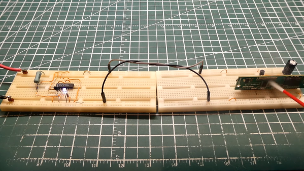
As with all things electronic, there are tradeoffs, which [0033mer] addresses in some detail in the video below. The basic setup for his use case is a PIC-based sensor — temperature, for this demo — that would be mounted in some remote location. The microcontroller needs to be powered, of course, and also needs to send a signal back to a central point to indicate whether the monitored location is within temperature specs. Both needs are accommodated by a single pair of wires and a tiny bit of additional circuitry. On one end of the twisted pair is a power supply and decoder circuit, which sends 9 volts up the line to power the PIC sensor. The decoder is based on a CD4538 dual monostable multivibrator, set up for an “on” time of one second. A trigger input is connected to the power side of the twisted pair going to the sensor, where a transistor connected to one of the PIC’s GPIO pins is set up to short the twisted pair together every half-second. Power to the PIC is maintained by a big electrolytic and a diode, to prevent back-feeding the controller. The steady 0.5-Hz stream of pulses from the sensor keeps resetting the timer on the control side. Once that stream stops, either through code or by an open or short condition on the twisted pair, the controller triggers an output to go high.

It’s a pretty clever system with very simple and flexible circuitry. [0033mer] says he’s used this over twisted-pair wires a couple of hundred feet long, which is pretty impressive. It’s limited to one bit of bandwidth, of course, but that might just be enough for the job. If it’s not, you might want to check out our primer on current-loop sensors, which are better suited for analog sensors but still share some of the fault-detection features.

Continue reading “Simple CMOS Circuit Allows Power And Data Over Twisted-Pair Wiring”

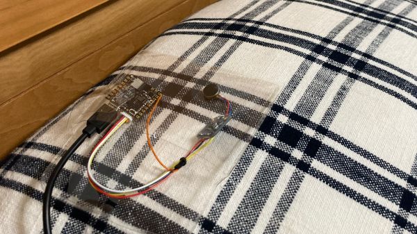
AI-Powered Snore Detector Shakes The Pillow So You Won’t

If you snore, you’ll probably find out about it from someone. An elbow to the ribs courtesy of your sleepless bedmate, the kids making fun of you at breakfast, or even the lady downstairs calling the cops might give you the clear sign that you rattle the rafters, and that it’s time to do something about it. But what if your snores are a bit more subtle, or you don’t have someone to urge you to roll over? In that case, this AI-powered haptic snore detector might be worth building.

The most distinctive characteristic of snoring is, of course, its sound, and that’s exactly what [Naveen Kumar] chose as a trigger. To differentiate between snoring and other nighttime sounds, [Naveen] chose an Arduino Nicla Voice sensor board, which sports a Syntiant NDP120 deep-learning processor and a built-in MEMS microphone. To generate a model that adequately represents the full tapestry of human snores, a publicly available snoring dataset — because of course that’s a thing — was used for training. Importantly, the training data included samples of non-snoring sounds, like sirens and thunder, as well as clips of legit snoring mixed with these other sounds. The model is trained with an online tool and downloaded onto the board; when it detects the sweet sound of sawing wood three times in a row, a haptic driver board vibrates the pillow as a gentle reminder to reposition. Watch it in action in the brief video below.

Snoring is something that’s easy to make light of, but in all seriousness, it’s not something to be taken lightly. Hats off to [Naveen] for developing a tool like this, which just might let you know you’ve got a problem that bears a closer look by a professional. Although it might work better as a wearable rather than a pillow-shaker.

Continue reading “AI-Powered Snore Detector Shakes The Pillow So You Won’t”

Solar Powered Flower Chases The Light

Many plants are capable of tracking the sun in order to get the most possible light. [hannu_hell] built a solar powered sculpture that replicates this light sensitivity for the benefit of better charging its own batteries, allowing it to run theoretically indefinitely where suitable light was available.

The 3D-printed flower features six movable petals mounted on an articulated stem. The flower’s leaves themselves bear solar panels that collect energy, analogous to leaves on a plant. A Raspberry Pi Pico is at the heart of the show, which is outfitted with a DS1307 real-time clock and a ST7735 TFT display for displaying date and time information. It’s also responsible for controlling servos that aim the flower’s solar panels towards the brightest light source available. This is achieved by using the Pico to read several photoresistors to determine light levels and adjust the leaves accordingly.

It’s a fun build, and one that could teach useful lessons relevant to even large-scale solar arrays. Video after the break.

Continue reading “Solar Powered Flower Chases The Light”

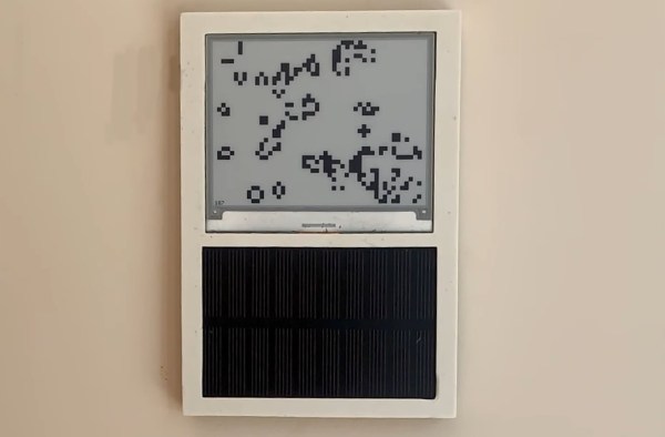
An E-ink display showing Conway's Game of Life, with a solar cell beneath it

Solar Powered Game Of Life Follows The Sun’s Rhythm

Conway’s Game of Life is a beautiful example of how complex behavior can emerge from a few very simple rules. But while it uses biological terminology such as “cells”, “alive” and “generation”, the basic game is too simplistic to be a model for any real-world biological process. It’s easy to add features to make it a bit more life-like, however, as [David Hamp-Gonsalves] has done by giving the Conway’s creation something of a circadian rhythm.

The basic idea is that the speed at which [David]’s Game of Life evolves is governed by the amount of ambient light. The game runs off a solar cell that charges a battery, with the battery’s voltage determining how long it takes to advance the game by one generation. The system is therefore highly active in full sunlight, and grinds almost to a complete halt at night.

An ESP32 runs the simulation and outputs the result to a 400 x 300 pixel e-ink display. The display is extremely power-efficient by its very nature; the ESP’s main processor core, on the other hand, is deliberately placed into deep sleep mode most of the time to save as much power as possible. The Ultra Low Power (ULP) co-processor, meanwhile, keeps an eye on the lithium battery’s voltage as it’s slowly being charged by the solar cell. When the voltage reaches 3.3 V, the main CPU wakes up and computes the Game’s new state. In bright sunlight this happens every few seconds, while on an overcast day it could take minutes or even hours.

[David]’s interesting idea of changing Life‘s activity based on the amount of energy available turns the Game into something resembling a cold-blooded animal. We’ve seen a similar approach in a “solar creature” that runs a Life-life simulation on a seven-segment LCD. If it’s speed you care about however, you’re better off implementing Life in an FPGA.