We all love seeing data represented in pretty ways — whether it’s necessary or not. Take VU meters for example. They’re a super useful tool for audio editors to balance signals, but they also look really cool, even if you’re only listening to music. Who didn’t use a Winamp skin with a built-in VU meter back in the day? Even after the demise of everyone’s favorite media player, we still see these great graphs popping up all over the place.
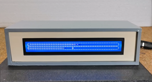
Most recently, we’ve seen VU meters circle back around to have a bit of a retro vibe in this awesome Arduino-controlled LCD VU meter built by [mircemk]. Based on the KTAudio VU Meter project, it features an ultra-wide LCD, audio input, and volume knob, all tidily wrapped up in a case whose color scheme that can only conjure images of the famed Altair 8800, or an old Tektronix oscilloscope. The LCD itself is fairly responsive — but you can judge for yourself in the video below. The signature fading that so commonly accompanies screen refreshes on LCDs such as this one really adds to the retro effect.
You may just need one of these displays on your desk — after all, while you may not need to know how loud each audio channel is, don’t you at least want the information available? Just in case. Bar graph display a bit too modern-looking for you? Well then you should check out [mircemk]’s OLED version that displays dual analog meters.