Many of the games released on the Nintendo 64 have aged remarkably well, in fact a number of them are still considered must-play experiences to this day. But the years have not been so kind to the system’s signature controller. While the N64 arguably defined the console first person shooter (FPS) genre with games like “Goldeneye” and “Perfect Dark”, a modern gamer trying to play these classics with the preposterous combination of analog and digital inputs offered by the N64 controller is unlikely to get very far.
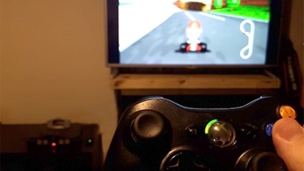
 Of course, you could play N64 games in an emulator and use whatever controller you wish. But where’s the challenge in taking the easy way out? [Ryzee119] would much rather take the insanely complex route, and has recently completed work on an add-on board that let’s you use Xbox 360 wireless controllers on Nintendo’s 1996 console. He’s currently prepping schematics and firmware for public release, with the hope that support for additional USB controllers can be added by the community.
Nintendo historians may recall that the N64’s controllers had an expansion port on the bottom where you would connect such accessories as the “Rumble Pak” and “Controller Pak”. The former being an optional force feedback device, and the latter a rather oddly named memory card for early N64 games which didn’t feature cartridge saves. Only “90’s Kids” will recall the struggle of using the “Rumble Pak” when a game required the “Controller Pak” to save progress.
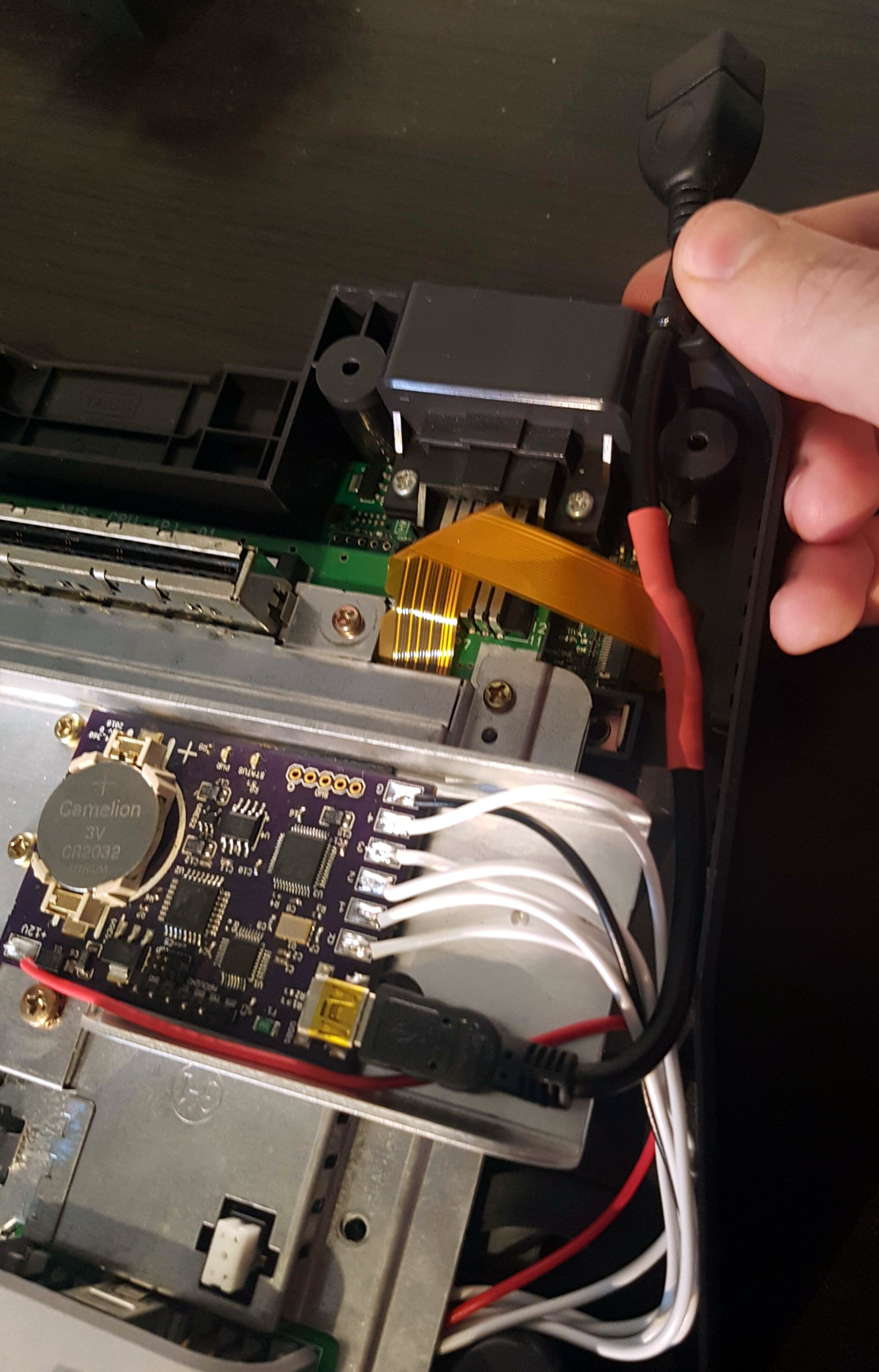
Thankfully [Ryzee119] has solved that problem by adding battery backed storage to his adapter along with some clever code which emulates the “Controller Pak”. Similarly, the “Rumble Pak” is emulated by the Xbox 360 controller’s built-in force feedback and a bit of software trickery. Specific button combinations allow for enabling and disabling the various virtual accessories on the fly.
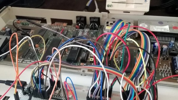
But the best part of this modification might be how unobtrusive the whole thing is. Not only does it allow you to still use the original controllers and accessories if you wish, but it only requires soldering a handful of wires to the console’s motherboard. Thanks to the surprising amount of dead space inside the system’s case, it’s not even a challenge to fit the board inside. You do need to use the official USB Xbox 360 controller receiver, but even here [Ryzee119] opted to put a USB port on the board so you could just plug the thing in rather than having to cut the connector off and trying to solder it to the board yourself.
It probably won’t come as a surprise that this isn’t the first time [Ryzee119] has fiddled with the internals of a classic Nintendo system. We’ve previously covered his fantastic custom PCB to fit a Raspberry Pi Zero into a GameBoy Advance.
[Thanks to Gartral for the tip.]