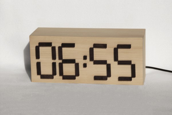
[BrittLiv] and her boyfriend got in one too many fights about who set the alarm. It’s the only argument they seem to repeat. So, true to her nature as an engineer, she over-engineered. The result was this great puzzle alarm clock.
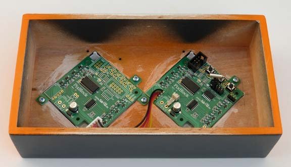
The time displayed on the front is not the current time. Since the argument was about alarm times in the first place, [BrittLiv] decided the most prominent number should be the next alarm. To hear the time a button (one of the dots in the colon) must be pressed on the front of the clock. To set the alarm, however, one must manually move the magnetized segments to the time you’d like to get up. Processing wise, for a clock, it’s carrying some heat. It runs on an Intel Edison, which it uses to synthesize a voice for the time, news, weather, and, presumably, tweets. It sounds great, check it out after the break.
All in all the clock looks great, and works well too. We hope it brought peace to [BrittLiv]’s household.
Continue reading “Puzzle Alarm Clock Gets Couple Up In The Morning”
 e’ve featured a lot of clock builds, but this one, as the title suggests, is frickin’ amazing. Talented art student [