Learn Flip Flops With (More) Simulation

In the previous installment, we talked about why flip flops are such an important part of digital design. We also looked at some latch circuits. This time, I want to look at some actual flip flops–that is circuit elements that hold their state based on some clock signal.

Just like last time, I want to look at sequential building blocks in three different ways: at the abstraction level, at the gate level, and then using Verilog and two online tools that you can also use to simulate the circuits. Remember the SR latch? It takes two inputs, one to set the Q output and the other to reset it. This unassuming building block is at the heart of many other logic circuits.

circ5
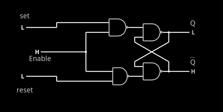
A common enhancement to the SR latch is to include an enable signal. This precludes the output from changing when the enable signal is not asserted. The implementation is simple. You only need to put an additional gate on each input so that the output of the gate can’t assert unless the other input (the enable) is asserted. The schematic appears on the right.

In the case of this simulation (or the Verilog equivalent), the SR inputs become active high because of the inversion in the input NAND gates. If the enable input is low, nothing will change. If it is high, then asserted inputs on the S or R inputs will cause the latch to set or reset. Don’t set both high at the same time when the enable is high (or, go ahead–it is a simulation, so you can’t burn anything up).(Note: If you can’t see the entire circuit or you see nothing in the circuit simulator, try selecting Edit | Centre Circuit from the main menu.)

Continue reading “Learn Flip Flops With (More) Simulation”

Hackaday Dictionary: The ESP8266

In August of 2014, something new started showing up in the markets of Shenzhen, the hi-tech area of China where the majority of the world’s electronics components are made. This is the ESP8266, a WiFi SoC (System on a Chip) that can connect to 802.11b/g/n networks on the 2.4GHz band. It can be addressed with SPI or a serial connection, and has an AT command set that makes it behave rather like an old-style modem. Basically, it has everything you would need to connect a device to a WiFi network, with the ESP8266 chip itself handling the complicated business of finding, joining and transmitting/receiving over a WiFi network.

That’s nothing particularly new in itself: WiFi connection devices like the TI CC3000 have been around for longer, and do much the same thing. The difference was the price. While the TI solution costs about $10 if you buy several thousand of them, the ESP8266 costs less than $7 for an individual board that can plug straight into an Arduino or similar. Buy the chip in bulk, and you can get it for less than $2.

The ESP8266 is more than just a WiFi dongle, though: it is a fully fledged computer in itself, with a megabyte of flash memory and a 32-bit processor that uses a RISC architecture. This can run applications, turning the ESP8266 into a standalone module that can collect and send data over the Internet. And it can do this while drawing a reasonably low amount of power: while receiving data, it typically uses just 60mA, and sending data over an 802.11n connection uses just 145mA. That means you can drive it from a small battery or other small power source, and it will keep running for a long time.

It wasn’t an easy ship to write applications for in the early days, though: it was poorly documented and required a dedicated toolchain to work with. This made it more of a challenge than many hackers were comfortable with.  That changed earlier this year, though, when the Arduino IDE (Integrated Development Environment) was ported to the chip. This meant that you could use the much easier to write Arduino functions and libraries to write code for the chip, bringing it within reach of even the most casual hacker.

Continue reading “Hackaday Dictionary: The ESP8266”

Learn Flip Flops With Simulation

Digital design with combinatorial gates like AND, OR, and NOT gates is relatively straightforward. In particular, when you use these gates to form combinatorial logic, the outputs only depend on the inputs. The previous state of the outputs isn’t important in combinatorial logic. While this is simple, it also prevents you from building things like state machines, counters, and even CPUs.

Circuits that use their own outputs as inputs are known as sequential circuits. It is true that at the fundamental level, sequential circuits use conventional logic gates. However, you usually won’t deal with them as gates, but will deal with abstractions like latches, flip flops, and even higher level constructs. Learning about these higher level constructs will allow you to make more advanced digital designs that are robust. In fact, if you are using an FPGA, building blocks like flip flops are essential since a large portion of the chip will be made up of some kind of flip flop.

Continue reading “Learn Flip Flops With Simulation”

Drawbacks Of Laser Cut Delrin–and How To Slip Around Them

Welcome back to part II in this ensemble of techniques with laser-cut Delrin. Thanks for many of the great insights along the way in the comments. In this guide, I’d like to go over some of the more immediate kinks that come to mind when getting started with this material.

Sourcing Delrin Sheets

When it comes to shopping, there are a variety of suppliers to choose from, but there are a few key words and thoughts to keep in mind.

Names

First, Delrin, is the “brand name” that refers to the Acetal homopolymer. Variants may also be labeled, acetal or acetal homopolymer. Delrin’s natural color is a soft white, but dyes can take it into a range of other colors. Black and white are, by far, the most common, though.

Tolerances

In the previous guide, all of the examples were cut from a small range of sheet thicknesses (0.0625[in], 0.09375[in], and .125[in]) sourced from OnlineMetals. As the thickness of the sheet increases, the tolerances on the thickness rating will also become more loose. You might buy a .125[in] plate and find it to be .124[in] in some places and .126[in] in others. If you purchase a .250[in] sheet, however, you’ll find that it may vary as much as .126[in] oversize though!

Buy it Flat

Despite McMaster-Carr being my go-to solution for one-off prototypes where rapid build iterations trump BOM cost, I don’t recommend purchasing Delrin from them as their sheets don’t have a flatness rating and often gets shipped bent in (oddly sized) boxes. (Seriously, has anyone else gotten a few oddly-sized parts in a gigantic McMaster-box before?)

Internal Stresses

Extruded Delrin has internal stresses built up inside of the sheet. There are a variety of reasons why this could be the case, but my biggest hunch is that the extrusion process at the factory results in different parts of the sheets solidifying at different times as the sheet cools, possibly causing some parts of the sheet to tighten from the cooling before other gooier sections have yet to finish cooling. What this means for you is that as your part gets lased out of the sheet, you’re, in a sense, relieving that stress. As a result, the part that you cut–especially for thin sheets–may come out of the laser cutter slightly warped.

Continue reading “Drawbacks Of Laser Cut Delrin–and How To Slip Around Them”

Embed With Elliot: Interrupts, The Good…

What’s the biggest difference between writing code for your big computer and a microcontroller? OK, the memory and limited resources, sure. But we were thinking more about the need to directly interface with hardware. And for that purpose, one of the most useful, and naturally also dangerous, tools in your embedded toolchest is the interrupt.

Interrupts do exactly what it sounds like they do — they interrupt the normal flow of your program’s operation when something happens — and run another chunk of code (an interrupt service routine, or ISR) instead. When the ISR is done, the microcontroller picks up exactly where it left off in your main flow.

Say you’ve tied your microcontroller to an accelerometer, and that accelerometer has a “data ready” pin that is set high when it has a new sample ready to read. You can wire that pin to an input on the microcontroller that’s interrupt-capable, write an ISR to handle the accelerometer data, and configure the microcontroller’s interrupt system to run that code when the accelerometer has new data ready. And from then on everything accelerometer-related happens automagically! (In theory.)

This is the first part of a three-part series: Interrupts, the Good, the Bad, and the Ugly. In this column, we’ll focus on how interrupts work and how to get the most out of them: The Good. The second column will deal with the hazards of heavyweight interrupt routines, priority mismatches, and main loop starvation: the Bad side of interrupts. Finally, we’ll cover some of the downright tricky bugs that can crop up when using interrupts, mainly due to a failure of atomicity, that can result in logical failures and corrupted data; that’s certainly Ugly.

Continue reading “Embed With Elliot: Interrupts, The Good…”

Learn And Build A High Side Switch

As electronics engineer I have a mental collection of circuits that I’ve gathered over the years, much like a mechanic collects specialized tools as they work. All engineers do this and the tools in their tool boxes usually represent their project history and breadth.

A useful circuit to have in designer’s toolbox is the “high side switch”. Like it sounds, this is a circuit that switches the “high side” or positive voltage to a load.

We usually tend to switch things to ground as seen by outputs such as an Open Collector output, the reason being that ground usually is a known entity and is usually low impedance and is at a known voltage. But there are advantages to using a high-side switch in your circuits.

Continue reading “Learn And Build A High Side Switch”

How To Build A Pocket-Sized MBed Signal Generator

Last month, I talked about how to get started with mBed and ARM processors using a very inexpensive development board. I wanted to revisit mBed, though, and show something with a little more substance. In particular, I often have a need for a simple and portable waveform generator. It doesn’t have to be too fancy or meet the same specs as some of the lab gear I have, but it should be easy to carry, power off USB, and work by itself when required.

My requirements mean I needed a slightly more capable board. In particular, I picked up a K64F board. This is very similar to the KL25Z board but has a bit more of everything–speed, memory, etc. What I really wanted, though, was the SD card slot. I did, however, do my early testing on a KL25Z, so if you have one, you can still work through the code, although standalone operation won’t be possible. The price jumps from $13 to $35, but you get a lot more capability for the price.

Continue reading “How To Build A Pocket-Sized MBed Signal Generator”