Turn That Pi Zero Into A Streaming Camera, Step-by-Step

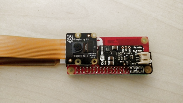
What makes [mwagner1]’s Raspberry Pi Zero-based WiFi camera project noteworthy isn’t so much the fact that he’s used the hardware to make a streaming camera, but that he’s taken care to document every step in the process from soldering to software installation. Having everything in one place makes it easier for curious hobbyists to get those Pi units out of a drawer and into a project. In fact, with the release of the Pi Zero W, [mwagner1]’s guide has become even simpler since the Pi Zero W now includes WiFi.

Using a Raspberry Pi as the basis for a WiFi camera isn’t new, but it is a project that combines many different areas of knowledge that can be easy for more experienced people to take for granted. That’s what makes it a good candidate for a step-by-step guide; a hobbyist looking to use their Pi Zero in a project may have incomplete knowledge of any number of the different elements involved in embedding a Pi such as basic soldering, how to provide appropriate battery power, or how to install and configure the required software. [mwagner1] plans to use the camera as part of a home security system, so stay tuned.

If Pi Zero camera projects catch your interest but you want something more involved, be sure to check out the PolaPi project for a fun, well-designed take on a Pi Zero based Polaroid-inspired camera.


CNC Turns Empty Cans Into Action Figures

[apollocrowe] at Carbide 3D (a company that does desktop CNC machines) shared a project of his that spent years being not-quite-there, but recently got dusted off and carried past the finish line. His soda can robot action figures were originally made by gluing a paper design to aluminum from a soda can, but [apollocrowe] was never really able to cut the pieces as reliably or as accurately as he wanted and the idea got shelved. With a desktop CNC machine to take care of accurate cutting, the next issue was how to best hold down a thin piece of uneven metal during the process. His preferred solution is to stick the metal to an acrylic wasteboard with hot glue, zero high enough and cut deep enough to account for any unevenness, and afterwards release the hot glue bond with the help of some rubbing alcohol.

Assembly involves minor soldering and using a few spare resistors. A small spring (for example from a retractable pen) provides the legs with enough tension for the figure to stand by itself. The results look great, and are made entirely from a few cents worth of spare parts and recycled materials. A video of the process is embedded below, and the project page contains the design files.

Continue reading “CNC Turns Empty Cans Into Action Figures”

Replica Fallout Terminal

If you’ve played Fallout 4, you’re familiar with the wall-mounted terminals in the game. They’ve got a post-apocalyptic aesthetic and the glowing green screen that calls out to anyone that grew up with computers and hacker movies from the 80s and 90s. Remember the first time you set your command line text to green? Don’t be embarrassed, we were all young once.

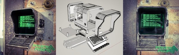
[PowerUpProps] liked the Fallout terminal so much they developed a replica. It’s a build that leans heavily on maker standards, a Raspberry Pi and 3D printing form the basis of the terminal. With ready access to such powerful tools, it makes starting such a project much more approachable. The key to the success of this build is the fine attention to detail in the finishing – the paint job looks incredible, and when photographed appropriately, it could be mistaken for the real thing an in-game screenshot.

An interesting touch is the use of a dark green acrylic window in front of the LCD, which gives the display a tinted hue. We’d like to see this compared with a clear glass window with a classic fishbowl curve to it, combined with greening up in software. The creator readily admits that this looks great at the command line, but is somewhat of a letdown when using the GUI.

Perhaps the only thing the prop build could use is some sort of user interface — the keyboard is only 3D printed and there’s no mouse or other pointing device included. There are some creative solutions to this problem, which we often see in other Fallout projects, like the ever popular Pip-Boy replica builds.

[Thanks to Sjoerd for the tip!]

Say It With Me: Aliasing

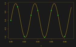
Suppose you take a few measurements of a time-varying signal. Let’s say for concreteness that you have a microcontroller that reads some voltage 100 times per second. Collecting a bunch of data points together, you plot them out — this must surely have come from a sine wave at 35 Hz, you say. Just connect up the dots with a sine wave! It’s as plain as the nose on your face.

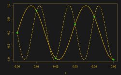
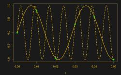
And then some spoil-sport comes along and draws in a version of your sine wave at -65 Hz, and then another at 135 Hz. And then more at -165 Hz and 235 Hz or -265 Hz and 335 Hz. And then an arbitrary number of potential sine waves that fit the very same data, all spaced apart at positive and negative integer multiples of your 100 Hz sampling frequency. Soon, your very pretty picture is looking a bit more complicated than you’d bargained for, and you have no idea which of these frequencies generated your data. It seems hopeless! You go home in tears.

But then you realize that this phenomenon gives you super powers — the power to resolve frequencies that are significantly higher than your sampling frequency. Just as the 235 Hz wave leaves an apparent 35 Hz waveform in the data when sampled at 100 Hz, a 237 Hz signal will look like 37 Hz. You can tell them apart even though they’re well beyond your ability to sample that fast. You’re pulling in information from beyond the Nyquist limit!

This essential ambiguity in sampling — that all frequencies offset by an integer multiple of the sampling frequency produce the same data — is called “aliasing”. And understanding aliasing is the first step toward really understanding sampling, and that’s the first step into the big wide world of digital signal processing.

Whether aliasing corrupts your pristine data or provides you with super powers hinges on your understanding of the effect, and maybe some judicious pre-sampling filtering, so let’s get some knowledge.

Continue reading “Say It With Me: Aliasing”

The Hard Way Of Cassette Tape Auto-Reverse

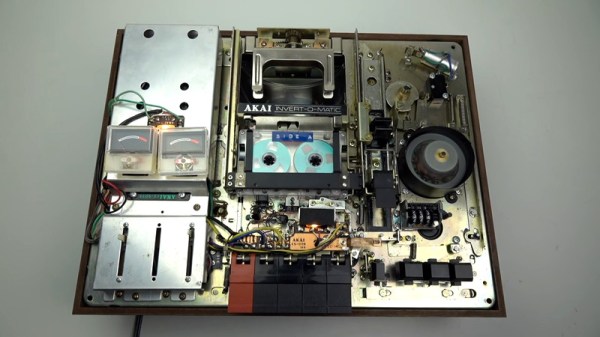
The audio cassette is an audio format that presented a variety of engineering challenges during its tenure. One of the biggest at the time was that listeners had to physically remove the cassette and flip it over to listen to the full recording. Over the years, manufacturers developed a variety of “auto-reverse” systems that allowed a cassette deck to play a full tape without user intervention. This video covers how Akai did it – the hard way.

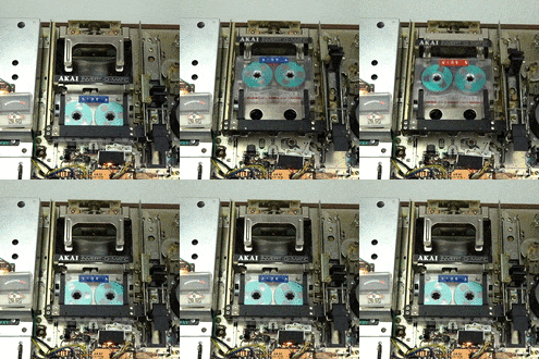
Towards the end of the cassette era, most manufacturers had decided on a relatively simple system of having the head assembly rotate while reversing the motor direction. Many years prior to this, however, Akai’s system involved a shuttle which carried the tape up to a rotating arm that flipped the cassette, before shuttling it back down and reinserting it into the deck.
Even a regular cassette player has an astounding level of complexity using simple electromechanical components — the humble cassette precedes the widespread introduction of integrated circuits, so things were done with motors, cams, levers, and switches instead. This device takes it to another level, and [Techmoan] does a great job of showing it in close-up detail. This is certainly a formidable design from an era that’s beginning to fade into history.

The video (found after the break) also does a great job of showing glimpses of other creative auto-reverse solutions — including one from Phillips that appears to rely on bouncing tapes through something vaguely resembling a playground slide. We’d love to see that one in action, too.

One thing you should never do with a cassette deck like this is use it with a cassette audio adapter like this one.

Continue reading “The Hard Way Of Cassette Tape Auto-Reverse”

How Does A Voltage Multiplier Work?

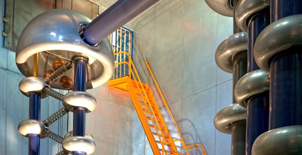
If you need a high voltage, a voltage multiplier is one of the easiest ways to obtain it. A voltage multiplier is a specialized type of rectifier circuit that converts an AC voltage to a higher DC voltage. Invented by Heinrich Greinacher in 1919, they were used in the design of a particle accelerator that performed the first artificial nuclear disintegration, so you know they mean business.

Theoretically the output of the multiplier is an integer times the AC peak input voltage, and while they can work with any input voltage, the principal use for voltage multipliers is when very high voltages, in the order of tens of thousands or even millions of volts, are needed. They have the advantage of being relatively easy to build, and are cheaper than an equivalent high voltage transformer of the same output rating. If you need sparks for your mad science, perhaps a voltage multiplier can provide them for you.

Continue reading “How Does A Voltage Multiplier Work?”

Dartboard Watches Your Throw; Catches Perfect Bullseyes

Some people really put a lot of effort into rigging the system. Why spend years practicing a skill and honing your technique to hit a perfect bullseye in darts when you can spend the time building an incredibly complicated auto-bullseye dartboard that’ll do it for you?

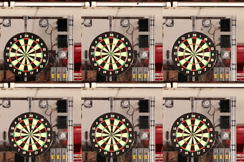
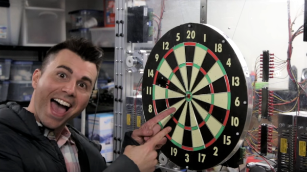
In fairness, what [Mark Rober] started three years ago seemed like a pretty simple task. He wanted to build a rig to move the dartboard’s bullseye to meet the predicted impact of any throw. Seems simple, but it turns out to be rather difficult, especially when you choose to roll your own motion capture system.



That system, built around the Nvidia Jetson TX1, never quite gelled, a fact which unfortunately burned through the first two years of the project. [Mark] eventually turned to the not inexpensive Vicon Vantage motion capture system with six IR cameras. A retroreflector on the non-regulation dart is tracked by the system and the resulting XY data is fed into MATLAB to calculate the parabolic path of the dart. An XY-gantry using six steppers quickly shifts the board so the bullseye is in the right place to catch the incoming dart.

It’s a huge amount of work and a lot of money to spend, but the group down at the local bar seemed to enjoy it. We wonder if it can be simplified, though. Perhaps tracking just the thrower’s motions with an IMU-based motion capture system and extrapolating the impact point would work.

Continue reading “Dartboard Watches Your Throw; Catches Perfect Bullseyes”