This excellent content from the Hackaday writing crew highlights recurring topics and popular series like Linux-Fu, 3D-Printering, Hackaday Links, This Week in Security, Inputs of Interest, Profiles in Science, Retrotechtacular, Ask Hackaday, Teardowns, Reviews, and many more.
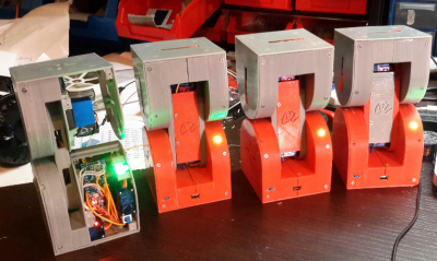
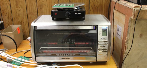
There are a variety of methods for reflowing a circuit board, but they all rely on a single principle: heat up the solder paste (a mixture of flux and solder) until the flux burns off and the solder becomes liquid, and then cool it down. Accomplishing this once or twice is easy; once you’ve played with a hot plate you’ll swear off through hole. Scaling it up and doing it repeatedly with high yield is extremely challenging, though. Continue reading “Tools Of The Trade – Reflow”→
In the early days of broadcast television, national spectrum regulators struggled to reconcile the relatively huge bandwidth required by the new medium with the limited radio spectrum that could be allocated for it. In the USA during the years immediately following World War Two there was only a 12-channel VHF allocation, which due to the constraints of avoiding interference between adjacent stations led to an insufficient number of possible transmitter sites to cover the entire country. This led the FCC in 1949 to impose a freeze on issuing licences for new transmitters, and left a significant number of American cities unable to catch their I Love Lucy or The Roy Rogers Show episodes.
The solution sought by the FCC was found by releasing a large block of UHF frequencies between 470 and 890 MHz from their wartime military allocation, and thus creating the new channels 14 to 83. An experimental UHF pilot station was set up in Bridgeport, Connecticut in 1949, and by 1952 the FCC was ready to release the freeze on new licence applications. The first American UHF station to go on air was thus KPTV in Portland, Oregon, on September 18th of that year.
UHF TV was a very new technology in 1952, and was close to the edge of what could be achieved through early 1950s consumer electronics. Though the 525-line TV standard and thus the main part of the sets were the same as their VHF counterparts, the tuner designs of the time could not deliver the performance you might expect from more recent sets. Their noise levels, sensitivity, and image rejection characteristics meant that UHF TV reception did not live up to some of its promise, and thus a fierce battle erupted between manufacturers all keen to demonstrate the inferiority of their competitors’ products over the new medium.
The video below the break delivers a fascinating insight into this world of claim and counter-claim in 1950s consumer electronics, as Zenith, one of the major players, fires salvos into the fray to demonstrate the superiority of their products over competing models or UHF converters for VHF sets. It’s very much from the view of one manufacturer and don’t blame us if it engenders in the viewer a curious desire to run out and buy a 1950s Zenith TV set, but it’s nonetheless worth watching.
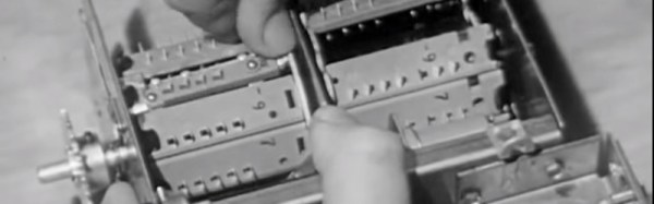
A key plank of the Zenith argument concerns their turret tuner. The turret tuner was a channel selection device that switched the set’s RF front end between banks of coils and other components each preset to a particular TV channel. Zenith’s design had a unique selling point that it could be fitted with banks of components for UHF as well as VHF channels thus removing the need for a separate UHF tuner, and furthermore this system was compatible with older Zenith sets so existing owners had no need to upgrade. Particularly of its time in the video in light of today’s electronics is the section demonstrating the clear advantages of Zenith’s germanium mixer diode over its silicon equivalent. Undeniably true in that narrow application using the components of the day, but not something you hear often.
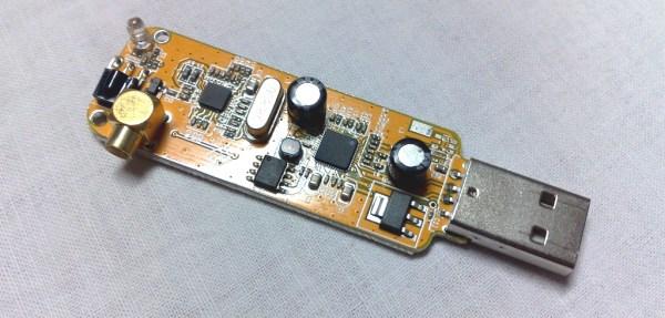
We are entering a new era of radio technology. A new approach to building radios has made devices like multi-band cell phones and the ubiquitous USB TV receivers that seamlessly flit from frequency to frequency possible. That technology is Software Defined Radio, or SDR.
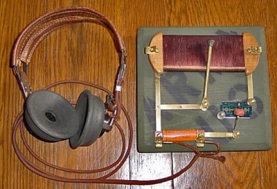
A idealized radio involves a series of stages. Firstly, an antenna receives the radio signal, converting it into an electrical signal. This signal is fed into a tuned resonator which is tuned to a particular frequency. This amplifies the desired signal, which is then sent to a demodulator, a device which extracts the required information from the carrier signal. In a simple radio, this would be the audio signal that was encoded by the transmitter. Finally, this signal is output, usually to a speaker or headphones.
A replica foxhole crystal set. Photo: Bill Jackson
That’s how your basic crystal radio works: more sophisticated radios will add features like filters that remove unwanted frequencies or additional stages that will process the signal to create the output that you want. In an FM radio, for example, you would have a stage after the demodulator that detects if the signal is a stereo one, and separates the two stereo signals if so.
To change the frequency that this radio receives, you have to change the frequency that the resonator is tuned to. That could mean moving a wire on a crystal, or turning a knob that controls a variable capacitor, but there has to be a physical change in the circuit. The same is true of the additional mixing stages that refine the signal. These circuits may be embedded deeply in the guts of the radio, but they are still there. This is the limitation with normal receivers: the radio can’t receive a signal that is outside the range that the resonator circuit can tune to, or change the way it is demodulated and processed. If you want to receive multiple frequency bands or different types of signals, you need to have separate pathways for each band or type of signal, physically switching the signal between them. That’s why you have physical AM/FM switches on radios: they switch the signal from an AM radio processing path to an FM one.
Software Defined Radios remove that requirement. In these, the resonator and demodulator parts of the radio are replaced by computerized circuits, such as analog to digital converters (ADCs) and algorithms that extract the signal from the stream of data that the ADCs capture. They can change frequencies by simply changing the algorithm to look for another frequency: there is no need for a physical change in the circuit itself. So, an SDR radio can be tuned to any frequency that the ADC is capable of sampling: it is not restricted by the range that a resonator can tune to. Similarly, the demodulator that extracts the final signal you want can be updated by changing the algorithm, changing the way the signal is processed before it is output.
This idea was first developed in the 1970s, but it didn’t really become practical until the 1990s, when the development of flexible field-programmable gate array (FPGA) chips meant that there was enough processing power available to create single chip SDR devices. Once programmed, an FPGA has no problem handing the complex tasks of sampling, demodulating and processing in a single device.
Most modern SDRs don’t just use a single chip, though. Rather than directly converting the signal to digital, they use an analog front end that receives the raw signal, filters it and converts it down to a fixed frequency (called the intermediate frequency, or IF) that the ADCs in the FPGA can more easily digitize. This makes it cheaper to build: by converting the frequency of the signal to this intermediate frequency, you can use a simpler FPGA and a cheaper ADC, because they don’t have to directly convert the maximum frequency you want to receive, only the IF. As long as the front end can convert a band of signals down to an intermediate frequency that the FPGA can digitize, the SDR can work with it.
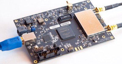
The BladeRF, a modern SDR device that can receive and transmit signals between 300 MHz and 3 GHz
This flexibility means that SDR devices can handle a huge range of signals at relatively low cost. The $420 BladeRF, for instance, can receive and transmit signals from 300 MHz to 3.8 GHz at the same time, while the $300 HackRF One can work with signals from 1 MHz up to an incredible 6 GHz. The ability of the BladeRF to both receive and transmit means that you can use it to build your own GSM phone network, while the low cost of the HackRF One makes it a favorite of radio hackers who want to do things like make portable radio analyzers. Mass produced models are even cheaper: by hacking a $20 USB TV receiver that contains an SDR, you can get a radio that can, with a suitable antenna, do things like track airplanes or receive satellite weather images. And all of this is possible because of the idea of Software Defined Radio.
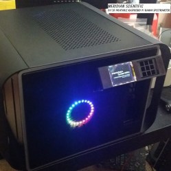
Humanity is better when we work together. Nowhere is this more true than when it comes to Citizen Scientists — the concept that scientific advancement isn’t reserved to the trained professionals, but benefits when a larger population of thinkers collaborates with the community of trained researchers. This is the goal of the Citizen Scientist challenge round for the Hackaday Prize. Let’s build something that enables citizens to be scientists.
We’ll divide $20,000 evenly between twenty projects that target Citizen Scientists. Enter now and build your prototype by July 11th for your chance to win. Even better, if you are selected as one of those 20 finalists you’ll compete for the top prizes, $150k and a residency at the Supplyframe Design Lab in Pasadena. Second through fifth place finishers will get $25k, $10k, $10k, and $5k.
You love design challenges and this one has powerful potential. We’ve seen builds like this in the finals during previous years of the Hackaday Prize. In 2014, RamanPi was recognized as the 5th place winner. The project seeks to reduce the expense of acquiring a Raman Spectrometer which is used for analyzing chemical substances. The design used parametric models for the optic jigs used by the machine. The idea is that a university could buy their own optics, adjust the models for the properties of those lenses and mirrors, then 3D print the parts to build the apparatus.
Also a winner in 2014, the Open Science Tricorder was recognized as the fourth place finisher. Based on the form factor and functionality of the iconic Star Trek technology, the Open Science Tricorder combines three or more sensor technologies with a user interface. It provides a hands-on experience for students learning about the properties of the world around them, and a handheld sensor suite to anyone interested in undertaking their own research projects.
The Citizen Scientist challenge round begins right now. Get started on your build today and show us what you can do to solve a technology problem with your prototyping skills. Good luck!
[fbustamante] got his hands on an old GP2X Wiz, one of those ARM-based portable media player/emulator things from a few years ago. This is a complete computer, and like the Pandora, it’ll do everything one of those Raspberry Pi laptops can do. The Wiz doesn’t have a keyboard, so [fbustamante] created his own. He etched his own PC, repurposed a keyboard controller from a USB keyboard, and stole the keycaps from an old Sharp digital organizer.
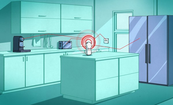
To the surprise of many, [Photonicinduction] is not dead. The drunk brit with a penchant for high voltage electrics and a very, very confused power company is back making videos again. His latest video is a puzzle. It’s a plastic block with a light bulb socket, a UK power outlet, and a switch. Plug in a light bulb, flip the switch, and it turns on. Plug a blender into the outlet, and that turns on too. No wires, so how is he doing it?
Introduced at CES last January, Monoprice – yes, the same place you get HDMI and Ethernet cables from – has released their $200 3D printer. This one is on our radar and there will be a review, but right away the specs are fantastic for a $200 printer. The build area is 120mm³, it has a heated bed, and appears to be not completely locked down like the DaVinci printers were a few years ago.
If you can’t tell, we’re on a roll with 3D printers and printed projects this month. So far, we’ve covered printers, and simple functional 3D prints. This week we’re taking a look at some of the awesome complex 3D printed projects on Hackaday.io.
Complex 3D printed projects are things like robots, quadcopters, satellite tracking systems, and more. So let’s jump in and look at some of the best complex 3D printed projects on Hackaday.io!
We start with [Alberto] and Dtto v1.0 Modular Robot. Dtto is [Alberto’s] entry in the 2016 Hackaday Prize. Inspired by Bruce Lee’s famous water quote, Dtto is a modular snake-like robot. Each section of Dtto is a double hinged joint. When two sections come together, magnets help them align. A servo controlled latch solidly docks the sections, which then work in unison. Dtto can connect and separate segments autonomously – no human required. [Alberto] sees applications for a robot like [Dtto] in search and rescue and space operations. Continue reading “Hacklet 109 – Complex 3D Printed Projects”→
So you’ve built a central server and filled your house with WiFi-connected nodes all speaking to each other using the MQTT protocol. In short, you’ve got the machine-to-machine side of things entirely squared away. Now it’s time to bring the humans into the loop! We’re going to explore a couple graphical user interfaces.
You could build a physical knob and/or LED display for every little aspect of your entire system, but honestly, this is where GUIs really shine. In this installment of Minimal MQTT, we’re going to look at human-friendly ways of consuming and producing data to interact with your connected sensors, switches, and displays. There are a ton of frameworks out there that use MQTT to build something like this, but we’re going to cut out the middle-man and go straight for some GUI MQTT clients.

 You love design challenges and this one has powerful potential. We’ve seen builds like this in the finals during previous years of the Hackaday Prize. In 2014,
 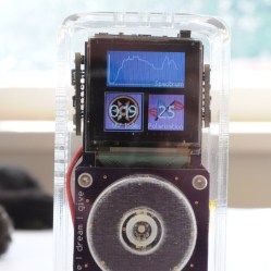 Also a winner in 2014, the