[Andrea De Napoli] created a LED display consisting of a half-dozen LEDs connected to the inverted signals of a CD4017 decade counter, giving the effect that a dark LED is running back and forth. The CD4017 works by activating 10 outputs, one at a time, as controlled by a clock signal sent to pin 14.
The first and last LEDs are lit by outputs 0 and 5 with the help of a PNP transistor and a 12K resistor. The middle four LEDs are switched by two outputs each and go dark when one of them goes high. [Andrea] really delves into the CD4017 and he shares a lot of detail in the project page.
If you’ve got a SEGA Dreamcast kicking around in a closet somewhere, and you still have the underutilized add-on Visual Memory Unit (VMU), you’re in for a treat today. If not, but you enjoy incredibly detailed hacks into the depths of slightly aged silicon, you’ll be even more excited. Because [Dmitry Grinberg] has a VMU hack that will awe you with its completeness. With all the bits in place, the hacking tally is a new MAME emulator, an IDA plugin, a never-before ROM dump, and an emulator for an ARM chip that doesn’t exist, running Flappy Bird. All in a month’s work!
The VMU was a Dreamcast add-on that primarily stored game data in its flash memory, but it also had a small LCD display, a D-pad, and inter-VMU communications functions. It also had room for a standalone game which could interact with the main Dreamcast games in limited ways. [Dmitry] wanted to see what else he could do with it. Basically everything.
We can’t do this hack justice in a short write-up, but the outline is that he starts out with the datasheet for the VMU’s CPU, and goes looking for interesting instructions. Then he started reverse engineering the ROM that comes with the SDK, which was only trivially obfuscated. Along the way, he wrote his own IDA plugin for the chip. Discovery of two ROP gadgets allowed him to dump the ROM to flash, where it could be easily read out. Those of you in the VMU community will appreciate the first-ever ROM dump.
On to doing something useful with the device! [Dmitry]’s definition of useful is to have it emulate a modern CPU so that it’s a lot easier to program for. Of course, nobody writes an emulator for modern hardware directly on obsolete hardware — you emulate the obsolete hardware on your laptop to get a debug environment first. So [Dmitry] ported the emulator for the VMU’s CPU that he found in MAME from C++ to C (for reasons that we understand) and customized it for the VMU’s hardware.
Within the emulated VMU, [Dmitry] then wrote the ARM Cortex emulator that it would soon run. But what ARM Cortex to emulate? The Cortex-M0 would have been good enough, but it lacked some instructions that [Dmitry] liked, so he ended up writing an emulator of the not-available-in-silicon Cortex-M23, which had the features he wanted. Load up the Cortex emulator in the VMU, and you can write games for it in C. [Dmitry] provides two demos, naturally: a Mandlebrot set grapher, and Flappy Bird.
Amazed? Yeah, we were as well. But then this is the same guy emulated an ARM chip on the AVR architecture, just to run Linux on an ATMega1284p.
At least one in their lives — or several times a day — everyone has wished they had a third hand to help them with a given task. Adding a mechanical extra arm to one’s outfit is a big step, so it might make sense to smart small, and first add an extra thumb to your hand.
This is not a prosthetic in the traditional sense, but a wearable human augmentation envisioned by [Dani Clode], a master’s student at London’s Royal College of Art. The thumb is 3D-printed out of Ninjaflex and mounted to a printed brace which slides over the hand. One servo rotates the thumb, and a second pulls it closed using a bowden cable system — not unlike that of a bicycle brake. Control of the thumb is achieved by pressure sensors in the wearer’s shoes, linked via Bluetooth to a wristband hosting the servos and the electronics. We already use our hands and feet in conjunction, so why not capitalize on this intuitive link?
Two hulking computers — likely necessitating the use of a crane to move them — and hundreds of tape reels were discovered in the basement of a former IBM engineer by their heir and a scrap dealer cleaning out the deceased’s home. Labels are scarce, and those that are marked are mostly from the late 1960s through the mid 1970s, including data from the Pioneer 8 to 11 missions, as well as the Helios missions.
What’s cooler than a door that irises open and closed? Not much. They add a nice science-fictiony detail to any entryway. [Zposner]’s dad wanted an automatic door for his chicken coop, so [zposner] took some time and came up with a nice door for him with an iris mechanism. You’ll need to watch the video.
[Zposner] used a combination of laser cutting and a CNC router to cut the pieces, then sanded and painted the wood. After assembly, [zposner] started work on the control mechanism. He’s controlling the door with an Arduino and a motor shield; to let the Arduino know to stop the motor, [zposner] used limit switches which get hit as the mechanism rotates. Once the switches were in the right place and the code written, it was time to finish assembly and install the door on the coop. To keep the Arduino that safe, it was installed in a plastic container with a screw lid, and then hot-glued to beside the iris.
Unfortunately, chickens don’t necessarily care how cool something is, and in this case, they didn’t realize that the iris was a door – they refused to exit the coop through it. [Zposner] tried a few things before settling on putting the chicken on the edge of the door – then the chicken would realize that it could go through it.
[Zposner]’s dad now has a snazzy door that opens with a switch. It was a great project for [zposner] and his dad to work on and, even if the chickens seem unimpressed, they did a great job. Check out the iris porthole that a Detroit Hackerspace built into its door, or, if you really want to build an iris mechanism, but don’t have access to a CNC router, a laser cutter, or, you know, wood, you could build this out of bits you have lying around.
Recently, the voice push to talk circuit in [Ryan]’s BITX40 radio was keyed down for a very long time. Blue smoke was released, a MOSFET was burnt out, and [Ryan] needed a new IRF510 N-channel MOSFET. Not a problem; this is a $1 in quantity one, but shipping from Mouser or Digikey will always kill you if you only buy one part at a time. Instead, [Ryan] found a supplier for five of these MOSFETs for $6 shipped. This was a good deal and a bad move because those new parts were fakes. Now we have an opportunity to play spot the fake MOSFET and learn that it’s all about the supply chain.
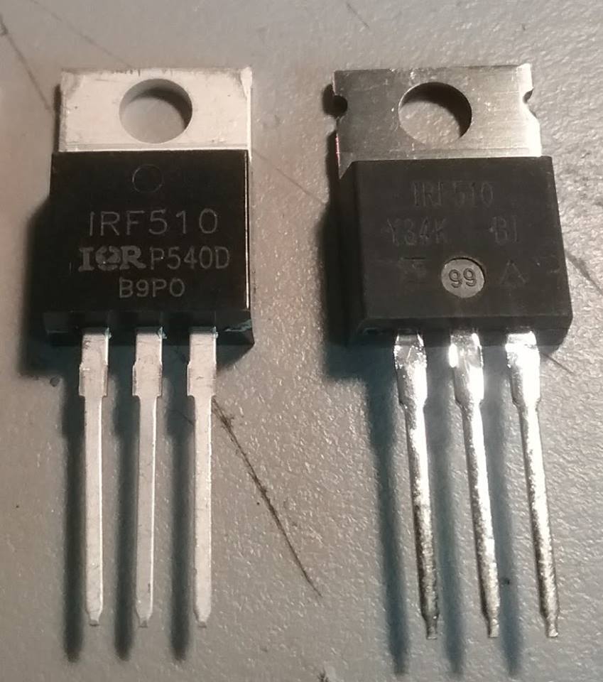
Spot the fake
To be fair to the counterfeit MOSFET [Ryan] acquired, it probably would have worked just fine if he were using his radio for SSB voice. [Ryan] is using this radio for digital, and that means the duty cycle for this MOSFET was 100% for two minutes straight. The fake got hot, and the magic blue smoke was released.
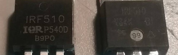
Through an industry contact, [Ryan] got a new, genuine IRF510 direct from Vishay Semiconductors. This is a fantastic opportunity to do a side-by-side comparison of real and counterfeit semiconductors, shown at right. Take a look: the MOSFET on the left has clear lettering, the one on the right has tinned leads and a notched heatsink. [Ryan] posed the question to a few Facebook groups, and there was a clear consensus: out of 37 votes, 21 people chose the MOSFET on the left to be genuine.
The majority of people were wrong. The real chip looked ugly, had tinned leads, and a thinner heatsink. The real chip looked like a poor imitation of the counterfeit chip.
What’s the takeaway here? Even ‘experts’ — i.e. people who think they know what they’re talking about on the Internet — sometimes don’t have a clue when it comes to counterfeit components. How can you keep yourself from being burned by counterfeit components? Stick to reputable resellers (Mouser, Digikey, etc) and assume that too good to be true is too good to be true.
If you need a sensor to detect gasses of some sort, you’ll probably be looking at the MQ series of gas sensors. These small metal cylinders contain a heater and some electrochemical sensor. Wire the heater up to a voltage, and connect one end of the resistor to an ADC, and you have a sensor for alcohol vapors, hydrogen sulfide, carbon monoxide, or ozone, depending on which model of sensor you’ve picked up.
There’s a difference between accuracy and precision, and if you want to calibrate gas sensors, you’ll need to calibrate them against something. Instead of digging out a gas sensor of known precision, [Davide] took the easy way out: he graphed the curves on the datasheets for these sensors. It’s brilliant in its simplicity.
These numbers were thrown into R, and with a bit of work, [Davide] had a look up table of various concentrations of gasses plotted against certain resistances. In testing these sensors, he found a higher correlation between humidity and temperature and gas concentrations, which one would expect.
The files for these sensors are available on [Davide]’s website, and he included a neat little video showing everyone what went into these calculations. You can check that out below.