Clap On! A Breadboard

The Clapper™ is a miracle of the 1980s, turning lights and TVs on and off with the simple clap of the hands, and engraving itself into the collective human unconsciousness with a little jingle that implores – nay, commands – you to Clap On! and Clap Off! [Rutuvij] and [Ayush] bought a clap switch kit, but like so many kits, this one was impossible to understand; building the circuit was out of the question, let alone understanding the circuit. To help [Rutuvij] and [Ayush] out, [Rafale] made his own version of the circuit, and figured out a way to explain how the circuit works.

While not the most important component, the most obvious component inside a Clapper is a microphone. [Rafale] is using a small electret microphone connected to an amplifier block, in this case a single transistor.

The signal from the microphone is then sent to the part of the circuit that will turn a load on and off. For this, a bistable multivibrator was used, or as it’s called in the world of digital logic and Minecraft circuits, an S-R flip-flop. This flip-flop needs two inputs; one to store the value and another to erase the stored value. For that, it’s two more transistors. The first time the circuit senses a clap, it stores the value in the flip-flop. The next time a clap is sensed, the circuit is reset.

Output is as simple as a LED and a buzzer, but once you have that, connecting a relay is a piece of cake. That’s the complete circuit of a clapper using five transistors, something that just can’t be done with other builds centered around a 555 timer chip.

Chaos Theory In Practice: Chua’s Circuit

Chua’s circuit is the simplest electronic circuit that produces chaos—the output of this circuit never repeats the same sequence, and is a truly random signal. If you need a good source of randomness, Chua’s circuit is easy to make and is built around standard components that you might have lying around. [Valentine] wrote a comprehensive guide which walks you through the process of building your own source of chaos.

The chaos of Chua’s circuit is derived from several elements, most importantly a nonlinear negative resistor. Unfortunately for us, this type of resistor doesn’t exist in a discrete form, so we have to model it with several other components. This resistor, also known as Chua’s diode, can be created with an op-amp configured as a negative impedance converter and a couple pairs of diodes and resistors. Other variations such, as the schematic above,22`01 model Chua’s diode using only op-amps and resistors.

The rest of the circuit is quite simple: only two capacitors, an inductor, and a resistor are needed. [Valentine] does note that the circuit is quite sensitive, so you might encounter issues when building it on a breadboard. The circuit is very sensitive to vibration (especially on a breadboard), and good solder connections are essential to a reliable circuit. Be sure to check out the Wikipedia article on Chua’s circuit for a brief overview of the circuit’s functionality and a rabbit trail of information on chaos theory.

Direct Digital Synthesis (DDS)

Direct Digital Synthesis (DDS) Explained By [Bil Herd]

One of the acronyms you may hear thrown around is DDS which stands for Direct Digital Synthesis. DDS can be as simple as taking a digital value — a collection of ones and zeroes — and processing it through a Digital to Analog Converter (DAC) circuit. For example, if the digital source is the output of a counter that counts up to a maximum value and resets then the output of the DAC would be a ramp (analog signal) that increases in voltage until it resets back to its starting voltage.

This concept can be very useful for creating signals for use in a project or as a poor-man’s version of a signal or function generator. With this in mind I set out here to demonstrate some basic waveforms using programmable logic for flexibility, and a small collection of resistors to act as a cheap DAC. In the end I will also demonstrate an off-the-shelf and inexpensive DDS chip that can be used with any of the popular micro-controller boards available that support SPI serial communication.

All of the topics covered in the video are also discussed further after the break.

Continue reading “Direct Digital Synthesis (DDS) Explained By [Bil Herd]”

Harmonic Analyzer Mechanical Fourier Computer

If you’re into mechanical devices or Fourier series (or both!), you’ve got some serious YouTubing to do.

[The Engineer Guy] has posted up a series of four videos (Introduction, Synthesis, Analysis, and Operation) that demonstrate the operation and theory behind a 100-year-old machine that does Fourier analysis and synthesis with gears, cams, rocker-arms, and springs.

In Synthesis, [The Engineer Guy] explains how the machine creates an arbitrary waveform from its twenty Fourier components. In retrospect, if you’re up on your Fourier synthesis, it’s pretty obvious. Gears turn at precise ratios to each other to create the relative frequencies, and circles turning trace out sine or cosine waves easily enough. But the mechanical spring-weighted summation mechanism blew our mind, and watching the machine do its thing is mesmerizing.

In Analysis everything runs in reverse. [The Engineer Guy] sets some sample points — a square wave — into the machine and it spits out the Fourier coefficients. If you don’t have a good intuitive feel for the duality implied by Fourier analysis and synthesis, go through the video from 1:50 to 2:20 again. For good measure, [The Engineer Guy] then puts the resulting coefficient estimates back into the machine, and you get to watch a bunch of gears and springs churn out a pretty good square wave. Truly amazing.

The fact that the machine was designed by [Albert Michelson], of Michelson-Morley experiment fame, adds some star power. [The Engineer Guy] is selling a book documenting the machine, and his video about the book is probably worth your time as well. And if you still haven’t gotten enough sine-wavey goodness, watch the bonus track where he runs the machine in slow-mo: pure mechano-mathematical hotness!

Continue reading “Harmonic Analyzer Mechanical Fourier Computer”

Running A Web Server On The ESP8266

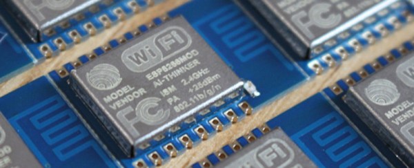
We’ve written lot about the ESP8266 lately, but people keep finding more awesome uses for this inexpensive module. [Martin] decided that using the ESP8266 with an external microcontroller was overkill, and decided to implement his project entirely on the module with a built-in web server.

[Martin] started out with the ESP8266 web server firmware developed by [sprite_tm]. This firmware provides a basic web server that supports multiple connections and simple CGI scripts right on the module. The web server firmware opens up a ton of possibilities with CGI scripting. When booting up in AP mode, you can even connect the ESP8266 to another access point right from the your browser.

[Martin] decided to connect a DHT22 temperature/humidity sensor to the module as a proof of concept. He used a DHT22 library written for the ESP8266 to read data from the sensor, and wrote a CGI script to display the data on a web page. [Martin] also added buttons to control a GPIO pin as a proof of concept. He posted his source code and a binary (see the end of his post) so you can try out his application and mod it for your own project.

Die image of the PCD8544 display controller

Photographing A Display Controller Die

Who doesn’t like integrated circuit porn? After pulling a PCD8544 display controller from an old Nokia phone, [whitequark] disrobed it and took the first public die shot.

As we’ve seen in the past, removing a die from its packaging can be a challenge. It typically involves nasty things like boiling acid. Like many display controllers, the PCD8544 isn’t fully encapsulated in a package. Instead, it is epoxied to a glass substrate.

Removing the glass proved to be difficult. [whitequark] tried a hot plate, a hot air gun, sulphuric acid, and sodium hydroxide with no success. Then the heat was turned up using MAPP gas, which burned the epoxy away.

After some cleaning with isopropanol, the die was ready for its photoshoot. This was done using a standard 30 mm macro lens. Photo processing was done in darktable, an open source photography tool and RAW processor.

[whitequark] plans to take closer photos in the future using more powerful magnification. These high resolution die photos can be useful for a number of things, including finding fake chips and reverse engineering retro hardware.

Hacking A $20 WiFi Smart Plug

The Kankun smart plug is an inexpensive device that lets you switch an outlet on and off over wifi. The smart plug only works with an Android or IOS app that ships with the device, which limits its usefulness to turning things on and off from your phone.

In an attempt to make this device more useful, [LinuxGeek] probed the device with nmap and discovered that it runs OpenWRT. After trying various common default passwords he discovered the login was root/admin. While [LinuxGeek] hasn’t sniffed the protocol yet, others have hacked it a bit further. The plug apparently uses UDP packets to communicate with the Android app, but the packets are unfortunately encrypted.

Rather than hack at the protocol, they wrote code that toggles the GPIO pin from a CGI script and developed a small Windows application that hits the CGI script for simple control from a computer. There’s also a Google+ group where more information and a couple other hacks for these plugs are posted. For $20 (from AliExpress) and with a bit of hacking, this smart plug could be a great way to add wireless control to a home automation system.