It’s official, we’re living in the future. Certainly that’s the only explanation for how [wrongbaud] was able to write a three-part series of posts on hacking a cheap electric toothbrush off of AliExpress.
As you might have guessed, this isn’t exactly a hack out of necessity. With a flair for explaining hardware hacking, [wrongbaud] has put this together as a practical “brush-up” (get it?) on the tools and concepts involved in reverse engineering. In this case, the Raspberry Pi is used as a sort of hardware hacking multi-tool, which should make it relatively easy to follow along.
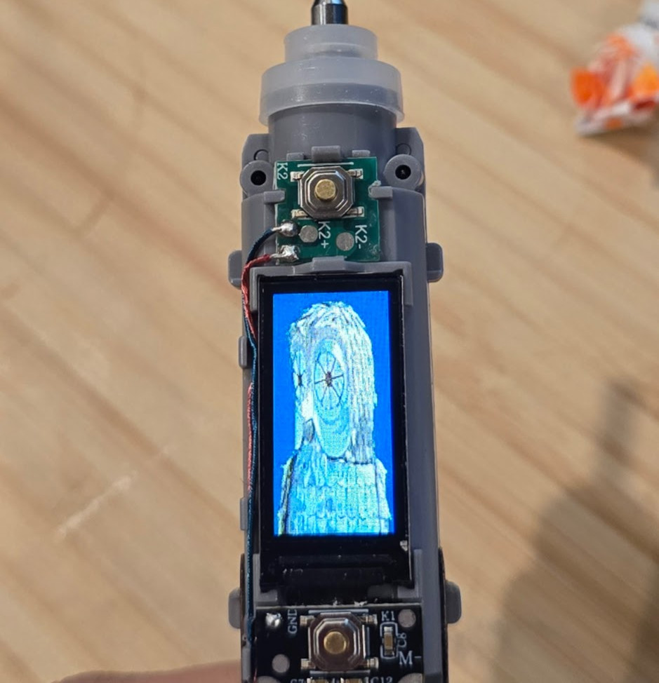
The first post in the series goes over getting the Pi up and running, which includes setting up OpenOCD. From there, [wrongbaud] actually cracks the toothbrush open and starts identifying interesting components, which pretty quickly leads to the discovery of a debug serial port. The next step is harassing the SPI flash chip on the board to extract its contents. As the toothbrush has a high-res color display (of course it does), it turns out this chip holds the images which indicate the various modes of operation. He’s eventually able to determine how the images are stored, inject new graphics data, and write it back to the chip.
Being able to display the Wrencher logo on our toothbrush would already be a win in our book, but [wrongbaud] isn’t done yet. For the last series in the post, he shows how to extract the actual firmware from the microcontroller using OpenOCD. This includes how to analyze the image, modify it, and eventually flash the new version back to the hardware — using that debug port discovered earlier to confirm the patched code is running as expected.
If you like his work with a toothbrush, you’ll love seeing what [wrongbaud] can do with an SSD or even an Xbox controller.